background image

Mechanical Operation and Maintenance Manual for ER180-4-3200 Industrial Robot

27

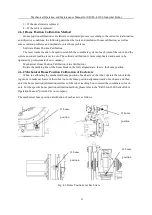
4.3 Inspection of the Lubricant

Inspect the iron powder concentration in the lubricant every 10000 hours or every 2 years. Replace the

lubricant or decelerator if the concentration exceeds 0.1%Wt. Please contact the service department when
in need.

Tools Needed

No.

Specifications

Remarks

1

OM-810 iron powder concentration meter

Manufactured by Idemitsu Kosan

2

Filling gun

The nozzle diameter should be less than 17mm and
should be equipped with a counting device.

3

Sealing tapes

/

Attention

In inspection, please supply with the filling gun if a certain amount of lubricant has
flowed out of the robot. The nozzle diameter should be less than 17 mm. The
lubricant supplied should not exceed the designated amount limit.

Attention

After inspection or refilling, please seal the pipe connection with sealing tapes. The
filling gun equipped with a counting device is recommended. Please check the
lubricant amount changes after refilling to ensure that it is within the designated
amount limit.

Attention

The inner pressure of the decelerator rises dramatically right after the

robot is stopped and the lubricant might squirt out once the inspection

screw is untightened. Lubricant should be refilled when the air pressure of

the decelerator is gradually released.

Attention

The lubricant should be constantly inspected to ensure its working

proficiency.

4.4 Change the Lubricant

4.4.1 The Oil Supply Quantity of Lubricant

Table 4-6 Oil Supply Table of Changing the Lubricant

Position

Amount

Name for the lubricant

Remarks

J1 axis decelerator

4500cc

MOLYWHITERE No.00

Rapid oiling will cause the pressure
in the oil tank to rise, the crack of
sealing ring, and the leakage of
lubricating oil . The oil supply speed
should be controlled below 40cc/10
seconds.

J2 axis decelerator

1100cc

J3 axis decelerator

1100cc

Component 1 of J3 axis

160cc

Component 2 of J3 axis

170cc

Wrist component

250cc

Содержание ER180-4-3200

Страница 1: ...1 ER180 4 3200 Mechanical Operation and Maintenance Manual for Industrial Robot EFORT Intelligent Equipment Co Ltd Service Line Tel 86 400 0528877...

Страница 2: ...e manual may result in physical damage or property loss The statement and instruction manual is the latest version for ER180 4 3200 series More updates can be found at www efort com cn This manual onl...

Страница 3: ...f Robots 7 Chapter Two Basic Description 8 2 1 Robot System Composition 8 2 2 Unpacking 8 2 3 Machine Body Nameplate 10 2 4 Body Composition and Direction Identification of Each Axis 10 2 5 Robot Axis...

Страница 4: ...g 18 3 2 4 Supporter Installation 20 3 2 5 Suspended Installation 20 3 3 Installation Environment 20 3 4 Integrated Connection Interface 21 Chapter Four Overhaul and Maintenance 25 4 1 Preventive Main...

Страница 5: ...ps for J1 J4 Axis Decelerator and Wrist Parts 28 4 4 4 Release the Residual Pressure in Lubricating Oil Cavity 30 4 5 Robot Maintenance and Use Area 30 4 6 Home Position Calibration 31 4 6 1 Home Posi...

Страница 6: ...lothes safety helmets safety shoes etc 2 When turning on the power make sure that there are no workers within the robot s operating range 3 The power must be cut off before entering the robot s range...

Страница 7: ...ncy situations generally have the following types 1 Low speed action suddenly becomes high speed action 2 Other operators performed the operation 3 A different program was started due to an abnormalit...

Страница 8: ...abnormal so as to ensure safe operation Warning The main body of the robot is a multi joint manipulator structure and the angle of each joint in the movement is constantly changing When you must appr...

Страница 9: ...ooling water outside the specifications which will affect the performance of the robot and cause abnormal operations malfunctions damage and other dangerous situations Attention Although electromagnet...

Страница 10: ...e at all times during operations It must be ensured that in an emergency you can escape immediately Attention Always pay attention to the actions of the robot and do not work with your back to the rob...

Страница 11: ...cidents such as falls Ensuring safety starts with tidying up 1 2 Shift Transfer and Sale of Robots Attention When the robot is shifted transferred or sold it is necessary to ensure that the auxiliary...

Страница 12: ...ard and components of the control device before discarding it Sharp parts such as cracks or cuts wires etc may cause injury Attention After the cables and external wiring are removed from the connecto...

Страница 13: ...ntrol Cabinet Teach pendant Connection power supply cables etc Fig 2 1 Industrial Robot System Composition 2 2 Unpacking Attention 1 Please check whether the packing remains intact or not before unpac...

Страница 14: ...16 m 20 m Control cabinet encoder cable 10900016328 1 SET Standard Length 8 m Customized Length 12 m 16 m 20 m Control cabinet brake cable 10900016327 1 SET Standard Length 8 m Customized Length 12 m...

Страница 15: ...eplate 2 4 Body Composition and Direction Identification of Each Axis The robot mechanical body is mainly composed of the base part the rotating part the big arm part the small arm part the wrist body...

Страница 16: ...d range limit When the robot system is running normally each axis of the robot is controlled to move within the allowable range In addition in order to ensure further safety mechanical end stops are p...

Страница 17: ...ntrol Axes 4 Axis Maximum Motion Speed Axis J1 104 sec Axis J2 104 sec Axis J3 104 sec Axis J4 210 sec Maximum Motion Rage Axis J1 175 Axis J2 40 86 Axis J3 60 52 Axis J4 360 Maximum Operation Radius...

Страница 18: ...Mechanical Operation and Maintenance Manual for ER180 4 3200 Industrial Robot 13 Figure 2 5 Motion Space of ER180 4 3200...

Страница 19: ...wrist payload should be strictly controlled within each allowable value When using the robot with a wrist payload other than the allowable value normal operation cannot be guaranteed 2 7 1 Allowable...

Страница 20: ...tion Please protect the cables when handling the robot and the control cabinet Besides the cables should be covered by a shield to prevent from accidental damage 3 1 2 Handling Method Position the rob...

Страница 21: ...Mechanical Operation and Maintenance Manual for ER180 4 3200 Industrial Robot 16 Fig 3 1 Lifting Sketch Map Fig 3 2 Forklifting Sketch Map v v...

Страница 22: ...hysical injury or property damage might occur 3 2 1 Setting up a Safety Fence The user of the robot should set up a safety fence according to the National Standards of the People s Republic of China o...

Страница 23: ...ess of the concrete ground should be no less than the depth of the buried chemical bolts and the concrete ground should cover the entire base area to ensure the safety and reliability of installation...

Страница 24: ...nd first We recommend that the thickness of the base plate should be more than 35mm Select 8 chemical bolts above M20 to fix the bottom plate on the ground The base of the robot is made of M20 with st...

Страница 25: ...pporter is less than 600 mm Install the supporter first and then fix the robot base to the supporter The connection strength and reliability between the supporter and the ground needs to be strictly v...

Страница 26: ...ontact the service department for robot protective covers if it is installed in an environment full of dust cutting oil and strong vibration 3 4 Integrated Connection Interface Table 3 2 External Conn...

Страница 27: ...ntenance Manual for ER180 4 3200 Industrial Robot 22 Fig 3 6 Dimensions for End Effector Interface Fig 3 7 Dimensions for Rotating Base Interface Fig 3 8 Dimensions for Big Arm Interface Installation...

Страница 28: ...re are two interfaces on the robot base the base interface and the external interface EFORT only offers the detailed dimensions and connection methods of these two interfaces The connectors screws and...

Страница 29: ...etailed dimensions for the end flange Please contact the relevant manufacturers for an end tool when in need 3 The standard dress package only include the motor cables and the encoder cables The dress...

Страница 30: ...and whether there is abnormal vibration 3 air cooling inspection check whether the fan behind the control cabinet is well ventilated 4 pipeline accessories inspection check whether it is complete whet...

Страница 31: ...ashes 2 Regarding the fastening parts tighten the end effector installing screws robot body installing screws and screws that have been removed for overhaul All screws exposed to the outside of the ro...

Страница 32: ...ng tapes The filling gun equipped with a counting device is recommended Please check the lubricant amount changes after refilling to ensure that it is within the designated amount limit Attention The...

Страница 33: ...Before performing the lubrication operation open the oil drain port remove the oil drain plug or screw plug 2 Provide lubricant slowly the oil supply speed should be controlled below 40cc 10 seconds...

Страница 34: ...tenance Manual for ER180 4 3200 Industrial Robot 29 J5 leakage of the supply and drain oil ports J1 oil drain port J2 oil drain port J1 oil drain port J2 oil filling port J1 oil filling port J3 oil dr...

Страница 35: ...t to avoid the spilled lubricating oil from scattering In order to release the residual pressure when the oil drain port is opened the J1 axis is in the range of 30 the J2 J3 axis is in the range of 5...

Страница 36: ...t of the safety fence is not less than 2 meters 2 Qualification requirements and precautions for maintenance personnel To enter the safety fence you must go through professional training When entering...

Страница 37: ...e operated by professionals of our company Mechanical Home Position Calibration Line Calibration Rotate the marking line of the home block to the fully aligned state that is the home position 4 6 2 Me...

Страница 38: ...er robot Position O ring rubber seal 170 3 55 1 Motor of axis J2 O ring rubber seal 122 2 65 1 Motor of axis J3 O ring rubber seal 87 5 2 65 3 Motor of axis J4 5 6 hexagon socket screw plug M10 1 15 o...

Страница 39: ...of axis J4 ER180 C104 04 02 1 Small arm component Table 4 Wrist Name Model Unit per robot Position Wrist ER180 C104 04 1 Wrist Table 5 Sealant and others Name Model Unit per robot Lubricant MOLYWHITE...

Страница 40: ...his product are subject to change without prior notice The technical data and illustrations are for reference only and we reserve the right to change them EFORT INTELLIGENT EQUIPMENT CO LTD No 96 Wanc...

Отзывы: