background image


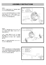
STEP 4: 

Attach the 

Rear Stabilizer (No.4)

 to the 

Sliding 

Rail  (No.2)

  using  4 

Bolts  (No.9)

,  4 

Spring 

Washers (No.8)

 and 4 

Washers (No.7)

. Tighten 

and secure with a 

Wrench (No.72)

Note: 

There  is  an  arrow  label  marked  in 

Rear 

Stabilizer (No.4)

, please attach it in the arrow’s 

direction. 


STEP 5: 

Connect 

Extension  Wire  (No.33) 

with  the 

Sensor Wire (No.30)

 
Fix


the

  Sliding  Rail  (No.2)

  to  the 

Main  Frame 

(No.1).

  First,  insert 

Bolt  (No.38) 

and

  Bolt 

(No.39) 

into  the  side  hole  of  the 

Main  Frame 

(No.1). 

Tighten


with  a

  Wrench  (No.72)

  and 

Wrench  (No.74). 

Then  screw 

Adjustable  Knob 

(No.41) 

with

  Washer  (No.40) 

to  tighten  the


Sliding  Rail  (No.2). 

Next  insert  the 

Pull  Pin 

(No.37). 


The assembly is complete! 


Содержание RW036

Страница 1: ...NGMACHINE USER MANUAL MODEL NO RW036 IMPORTANT Read all instructions carefully before using this product Save this manual for future reference EXERCISE EQUIPMENT QUESTIONS Contact customer service at...

Страница 2: ...dult use only Keep children and pets away from the machine DO NOT leave children unattended in the same room with the equipment 4 Use the equipment on a solid flat level surface with a protective cove...

Страница 3: ...3 EXPLODED DRAWING...

Страница 4: ...4 HARDWARE PACKAGE...

Страница 5: ...Wheel 39 92 3 54 Pulley 1 17 Nut M8 3 55 Nut M6 1 18 Round Magnet 18 4 1 56 Belt 1 19 Adjusting Bolt M6 36 4 57 Computer 1 20 U Bracket 31 30 1 0 4 58 Computer Cover 1 21 Spring Washer 6 4 59 Screw M5...

Страница 6: ...P 2 Insert the 2 Bolts No 34 into the bottom hole A of Main Frame No 1 Tighten with a Spanner No 75 Insert 2 Bolts No 34 through the Pedals No 35L R into the upper hole B of the Main Frame No 1 and ti...

Страница 7: ...4 please attach it in the arrow s direction STEP 5 Connect Extension Wire No 33 with the Sensor Wire No 30 Fix the Sliding Rail No 2 to the Main Frame No 1 First insert Bolt No 38 and Bolt No 39 into...

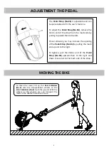
Страница 8: ...moved you may increase the opening of the Pedal Strap No 36 by pulling the mesh end up and to the right To tighten pull the Velcro end of the Pedal Strap No 36 upward then to the right and down to sec...

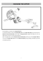
Страница 9: ...Wire No 33 and the wire of Computer No 57 Replace the battery Do not mix battery types and do not mix old and new batteries After the replacement connect Extension Sensor Wire No 33 with the wire of...

Страница 10: ...ll out the Pull Pin No 37 Lift slightly the Sliding Rail No 2 where it joins the Main Frame No 1 and fold the Sliding Rail No 2 to vertical angle Then insert the Pull Pin No 37 back to Sliding Rail No...

Страница 11: ...wing time from exercise start to end COUNT Counts the rowing strokes from start to end CALORIES Counts the total calories from rowing start to end REPS MIN Displays current rowing strokes per minute S...

Отзывы: