9
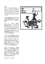
STEP 3:
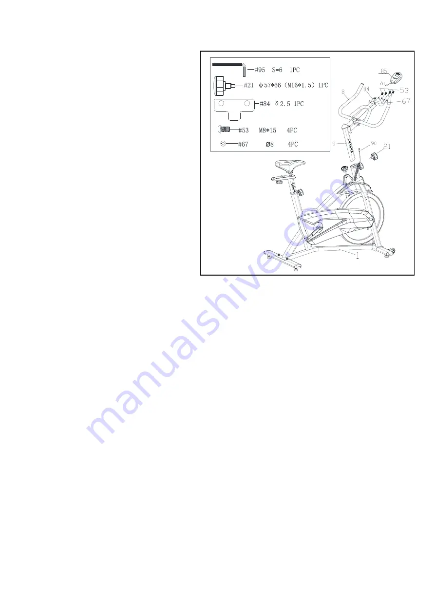
Insert the
Handlebar Post (No.9)
to
the
Main Frame (No.1)
. Set at desired
height, insert and tighten the
Adjustment Knob (No.21).
Attached
Handlebar (No.8)
and
Computer Bracket (No.84)
to the
Handlebar Post (No.9)
with 4
Bolts
(No.53)
and 4
Spring Washers
(No.67)
, then tighten with
Inner
Hexagon Spanner (No.95).
Note:
Make sure attach
Computer
Bracket (No.84)
on the upside 2 lock
holes in
Handlebar (No.8)
BATTERY INSTALLATION
: Open the
battery cover from the back of
Computer (No. 85)
, then put 1 pc
of
battery
into
the
battery
compartment. Make sure the (-) end
of the battery goes to the spring end
of the battery compartment, then put
the battery cover back. Attach the
Computer (No.85)
to the
Computer
Bracket (No.84)
, and connect the
computer wire A1 to
Sensor Wire
(No. 90)
together.
Содержание IC037
Страница 2: ......
Страница 4: ...3 EXPLODED DRAWING 1...
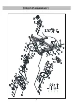
Страница 5: ...4 EXPLODED DRAWING 2...
Страница 8: ...7 HARDWARE PACKAGE...
Страница 19: ...18...
Страница 20: ...19...


