


UPS: OFFICE 400 - 2000
Installation and
Connection
OFFICE Series
28
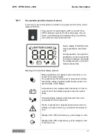
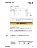
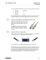
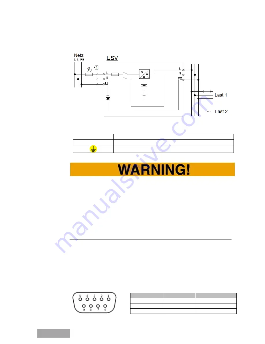
If a permanent connection of the UPS should be made, please pay attention to
the following connection diagram.
Fig. 5-3 Connection diagram of the UPS to the network and the loads.
(S)
Circuit breaker or fuse 10A;
(1)
Wire cross-section of the connection cable 0.75 mm²;
Grounding!
It is implicit to connect the protective conductor here and to maintain the loop
resistance all the way to the last load.
It is likewise possible to secure the loads separately against over and fault cur-
rents and to directly ground them.
Always pay attention to the correct polarity between input and output for the
UPS.
If the UPS is in the midst of an emergency stop circuit, it must be observed that
the UPS output is not completely currentless after the emergency stop circuit
operation. The loads will continue to be supplied by means of the duration of the
UPS autonomy time.
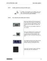
5.1.1
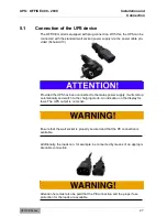
Connection of the device port RS232 (Communication interface)
The serial port RS232 serves to connect the UPS with a PC or rather the appli-
cation (software) installed on it
The connection is to be established by a standard serial cable. The configura-
tion is as follows (not listed pins are not assigned):
PC RS232:
USV RS232:
Function:
Pin 2
Pin 2
Tx USV, Rx PC
Pin 3
Pin 3
Rx USV, Tx PC
Pin 5
Pin 5
GND
Fig. 5-4 RS232 Connecting a device to the UPS (SubD 9pole, female).


