UPS MKD2000/3000 XL
Manual
MKD XL Series
Page 24 of 45
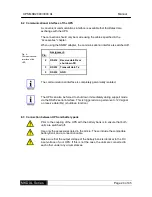
8.2 Communicational interface of the UPS
A convenient communications interface is available that facilitates data
exchange with the UPS.
The connection should only be made using the cables specified in the
“Accessories” chapter.
When using the SNMP adapter, the communicational interface is switched-off.
Fig. 6:
Communicational
interface of the
UPS
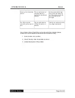
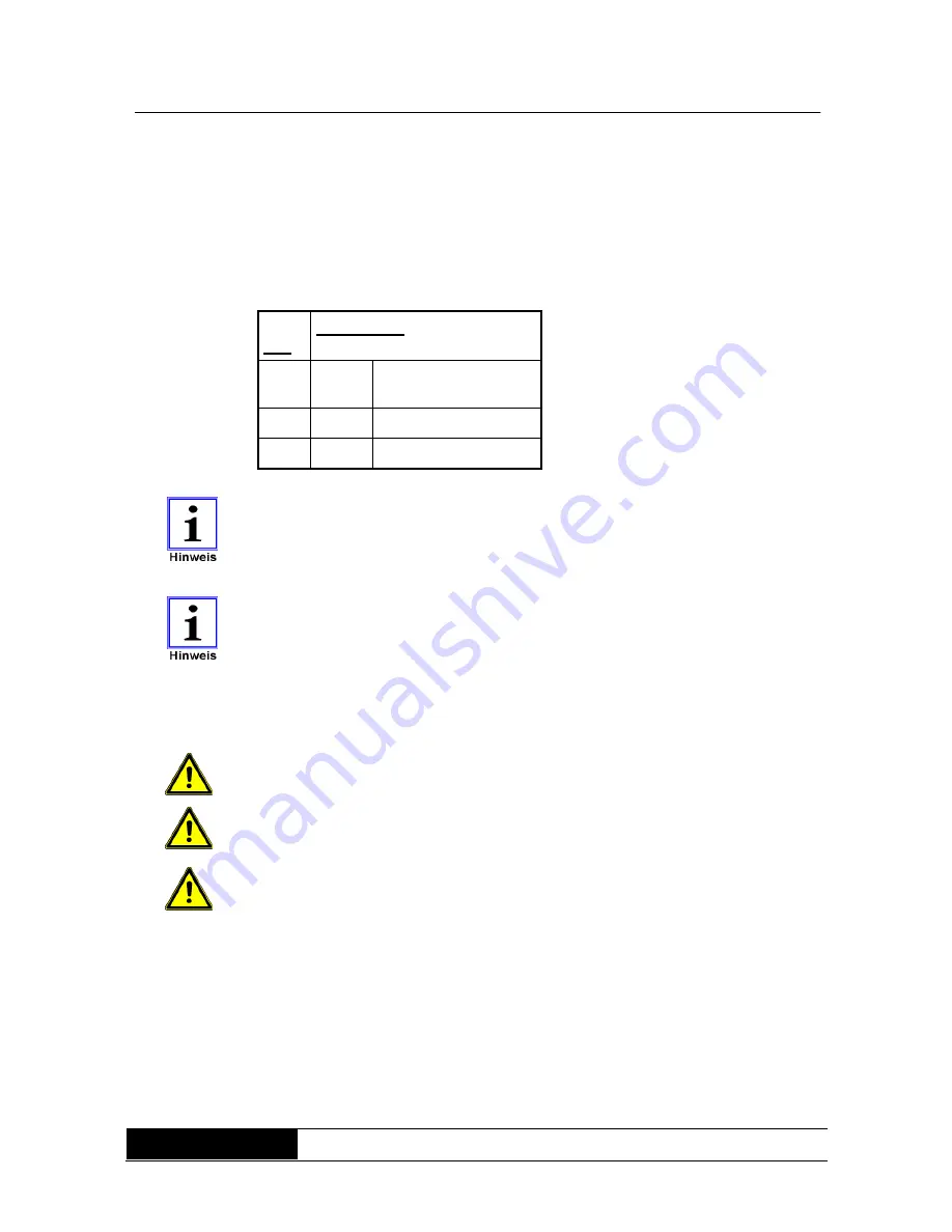
Pin:
Assignment:
2
RS232 Receive data Rx or
shut down SD
3
RS232 Transmit data Tx
5
RS232 GND
The communicational interface is completely galvanically isolated.
The UPS can also be forced to shut down immediately during support mode
via the RS232 serial interface. This is triggered via a per12V signal
on receive data (Rx) (shutdown function).
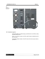
8.3 Connection between UPS and battery pack
Prior to the coupling of the UPS with the battery bank is to ensure that both
units are switched off.
Use only the accessories listed in the article. These include the compatible
battery bank and a connection cable.
Make sure that the output voltage of the battery bank is identical to the DC
input voltage of your UPS. If this is not the case, the units are connected to
each other under any circumstances.


