© Edwards Limited 2010. All rights reserved.
Page 9
Edwards and the Edwards logo are trademarks of Edwards Limited.
Technical data
A746-02-885 Issue A
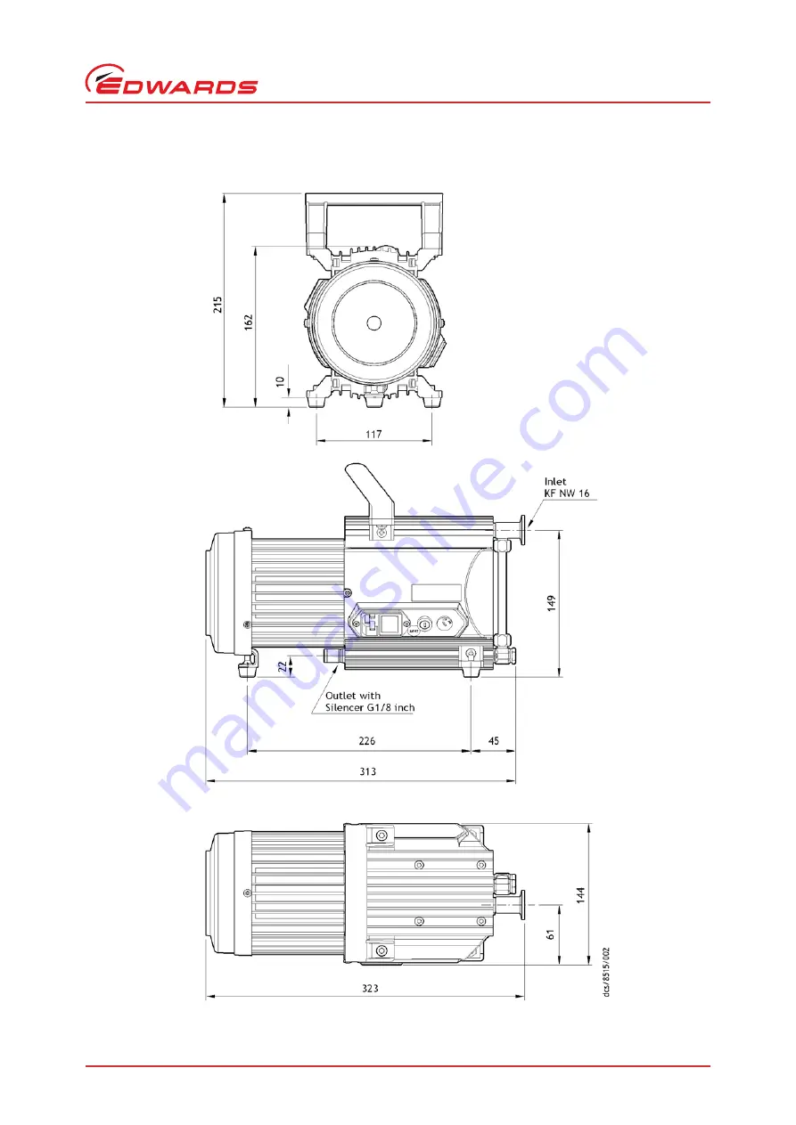
Figure 3 - Dimensional drawing XDD 1 (dual-voltage motor)
Страница 1: ...A746 02 885 Issue A Original Instruction Manual XDD 1 MKII 115 230 V and 24 V DC Diaphragm Pumps Description Item Number XDD 1 115 230 V A746 02 983 XDD 1 24 V A746 02 991 ...
Страница 2: ...2 1010 1 92 A2 97 Safety requirements for Electrical Equipment for Measurement Control and laboratory use Part 1 General requirements C22 2 61010 1 04 GI1 R2009 UL61010A 1 2002 Safety requirements for electrical equipment for measurement Control and laboratory use Part 1 General requirements UL61010 1 2004 R10 08 EN50581 2012 Technical Documentation for the Assessment of Electrical and Electronic ...
Страница 3: ...ed 14 4 Use and operation 15 4 1 Installing in a vacuum system 15 4 2 Prior to use 15 4 3 During operation 15 4 3 1 Pumps with dual voltage motor 15 4 3 2 Pumps with 24 V dc voltage 15 4 4 Shutdown 16 4 4 1 Short term 16 4 4 2 Long term 16 5 Maintenance 17 5 1 Replacing diaphragms and valves 17 5 1 1 Cleaning and inspecting the pump heads 20 5 1 2 Replacing the diaphragm 22 5 1 3 Assembling pump h...
Страница 4: ...move the housing cover and head cover 21 13 Remove the head cover from the housing cover 22 14 Lift the diaphragm 23 15 Position a new diaphragm 23 16 Diaphragm clamping disc 24 17 Assemble the diaphragm assembly to the connecting rod 24 18 Position the diaphragm 25 19 Assemble the head cover and valves 25 20 Scheme pump head with head covers 26 21 Scheme pump head with head covers and valves 26 2...
Страница 5: ... replace the protective covers Store the equipment in suitable conditions z Read and obey this manual before installing or operating the equipment z Transport the pump at the provided handle or the recessed grip The following symbols appear in this document Use the equipment for the intended use only i e for generation of vacuum z Prevent any part of the human body from coming in contact with the ...
Страница 6: ...e mean sea level conductive pollution or moisture WARNING Obey maximum permitted pressures and pressure differences see Section 2 Technical data Do not operate the pump with overpressure at the inlet WARNING Do not permit any uncontrolled pressurizing e g make sure that the exhaust pipeline cannot become blocked If you have an exhaust isolation valve make sure that you cannot operate the equipment...
Страница 7: ...fold pumped substances may leak into the environment or in the pump housing or the motor z Obey especially all notes on use and operation and on maintenance z Failure of the pump e g due to power failure must not lead to a critical dangerous situation under any circumstances Use only genuine spare parts and accessories z Otherwise safety and performance of the equipment as well as the electromagne...
Страница 8: ...and the Edwards logo are trademarks of Edwards Limited Introduction Figure 1 General view of XDD 1 with dual voltage motor 1 Handle removable 2 Inlet small flange NW16 3 Pump feet adjustable 4 Voltage selector switch 5 Fuse holder 6 Mains switch 7 Mains input 8 Outlet silencer ...
Страница 9: ... the Edwards logo are trademarks of Edwards Limited Introduction A746 02 885 Issue A Figure 2 General view of XDD 1 24 V DC 1 Cover of the circuit board 2 Inlet small flange NW 16 3 Male 15 pin D connector 4 Outlet silencer at lower side 5 Screw to secure cover ...
Страница 10: ...A746 02 885 Issue A Page 6 Edwards Limited 2010 All rights reserved Edwards and the Edwards logo are trademarks of Edwards Limited This page has been intentionally left blank ...
Страница 11: ...on Fuse 20 mm x 5 mm 250 V 2 5 A type T Table 2 Performance data Parameter XDD1 115 230 V 50 60 Hz XDD1 24 V DC Pumping speed ISO 21360 m3 h 1 2 1 4 1 7 2200 rpm 1 4 1700 rpm Factory set Ultimate vacuum absolute mbar 1 5 1 0 700 rpm No load speed min 1 1500 1800 100 2200 Maximum permissible outlet pressure absolute bar 1 1 Maximum pressure difference between inlet and outlet bar 1 1 Table 3 Enviro...
Страница 12: ...verall dimensions Refer to Figure 3 Refer to Figure 4 Inlet connection Small flange NW 16 Outlet connection Silencer G 1 8 inch Table 5 Materials data Components Wetted parts Housing cover Aluminium Head cover Aluminium Diaphragm clamping disc Aluminium Valve FPM e g Viton Diaphragm PTFE FPM e g Viton sandwich Inlet small flange Stainless steel Outlet silencer Aluminium silicon caoutchouc Hose PE ...
Страница 13: ... Edwards Limited 2010 All rights reserved Page 9 Edwards and the Edwards logo are trademarks of Edwards Limited Technical data A746 02 885 Issue A Figure 3 Dimensional drawing XDD 1 dual voltage motor ...
Страница 14: ...A746 02 885 Issue A Page 10 Edwards Limited 2010 All rights reserved Edwards and the Edwards logo are trademarks of Edwards Limited Technical data Figure 4 Dimensional drawing XDD 1 24 V DC ...
Страница 15: ...mains supply Figure 5 Adjust the supply voltage 1 Selecting 115 covers a voltage supply range of 100 V to 120 V 2 Selecting 230 covers a voltage supply range of 200 V to 240 V Ensure that the voltage shown on the voltage selector switch Figure 5 item 1 corresponds with your electrical supply voltage If it does not you must change the configuration of the pump motor using the voltage selector switc...
Страница 16: ...ed when connected to a 24 V DC 10 supply The pump can also be controlled using an external analogue 0 10 V signal Use a suitable connector mating half not supplied to connect the electrical supplies and your control equipment to the connector on the logic interface cable When you make the electrical connections to the XDD 1 refer to Table 6 for full details of the logic interface connections Table...
Страница 17: ...o positions Set to position 2 for normal speed or position 3 if maximum throughput is required refer to Figure 7 Assemble the cover in reverse order 3 3 Configuring the XDD1 24V dc for external analogue 0 10 V speed control Remove the screw which secures the cover to the circuit board refer to Figure 2 item1 Move the cover carefully and only as far as necessary Using a screw driver turn the potent...
Страница 18: ...peed Operating the pump at high motor speeds increases the pump throughput this will also cause the pump to generate more heat Ensure there is adequate ventilation especially when using the pump within confined spaces or enclosures Operating the pump at low motor speeds increases the ultimate vacuum performance this will also increase the lifetime of the diaphragm and valves ...
Страница 19: ... ventilation is adequate if pump is installed in a housing or if ambient temperature is elevated Keep a distance of min 20 cm between fans and ambient parts When assembling ensure vacuum tightness After assembly check the complete system for leaks 4 3 During operation CAUTION Do not start or operate the pump if pressure at the outlet is higher than 1 1 bar absolute Attempts to start or operate the...
Страница 20: ...n section short term shutdown z Separate pump from the apparatus z Close inlet and outlet port e g with transport caps z Store the pump in dry conditions Fault Action Has the pump been exposed to condensate Allow the pump to continue to run at atmospheric pressure with inlet open for a few minutes Has the pump been exposed to media which may damage the pump materials or forms deposits Check and cl...
Страница 21: ...ultimate vacuum is no longer achieved the pump interior the diaphragms and the valves must be cleaned and the diaphragms and valves must be checked for cracks or other damage Depending on individual cases it may be efficient to check and clean the pump heads on a regular basis In case of normal wear the lifetime of the diaphragms and valves is 10000 operating hours CAUTION Prevent internal condens...
Страница 22: ...late to the products processed by the pumping system The pump might be contaminated with the process chemicals that have been pumped during operation Ensure that the pump is decontaminated before maintenance and take adequate precautions to protect people from the effects of dangerous substances if contamination has occurred WARNING Wear appropriate safety clothing when you come in contact with co...
Страница 23: ...ademarks of Edwards Limited Maintenance A746 02 885 Issue A Figure 8 View of the disassembled pump head parts 1 Housing cover 2 VS seal 3 Bearing flange 4 Housing 5 Rod 6 Diaphragm support disc 7 Diaphragm 8 Diaphragm clamping disc with connecting screw 9 Head cover 10 Valve 11 VS seal ...
Страница 24: ...ed 5 1 1 Cleaning and inspecting the pump heads Use open ended wrench to remove fitting at the pump head and remove together with connecting hose Note Do not remove bearing flange 1 Figure 10 Remove the fitting at the pump head 1 Diaphragm key SW 46 included in service kit 2 Open ended wrench w f 14 3 Hex key w f 4 5 4 Phillips screw driver size 2 1 Bearing flange ...
Страница 25: ...move together with handle Figure 11 Remove the handle Use hex key to remove six socket head screws from pump head and remove upper housing housing cover and head cover Figure 12 Remove the housing cover and head cover WARNING Never remove parts by using a spiky or sharp edged tool e g screw driver we recommend to use a rubber mallet or compressed air to be blown carefully into port ...
Страница 26: ...Lift diaphragm carefully 2 Apply pressure to the clamping disc beside the diaphragm to bring connecting rod into upper turning point position if necessary 3 Use diaphragm key to grip under the diaphragm to the diaphragm support disc 4 Apply pressure to the diaphragm clamping disc to bring the diaphragm into lower turning point position Press diaphragm key against diaphragm clamping disc and unscre...
Страница 27: ...lamping disc with square head screw and diaphragm support disc Note Position diaphragm with white PTFE side to diaphragm clamping disc to pump chamber Figure 15 Position a new diaphragm 7 Lift diaphragm at the side and position carefully together with diaphragm clamping disc and diaphragm support disc in the diaphragm key CAUTION Avoid damage of the diaphragm Do not crack diaphragm in a way that l...
Страница 28: ...clamping disc is correctly seated in the guide hole of the diaphragm support disc 2 Assemble diaphragm clamping disc diaphragm and diaphragm support disc to connecting rod 3 Position washers if available between diaphragm support disc and rod Figure 17 Assemble the diaphragm assembly to the connecting rod 4 Bring diaphragm into a position in which diaphragm is in contact with housing and centred w...
Страница 29: ...of Edwards Limited Maintenance A746 02 885 Issue A Figure 18 Position the diaphragm 5 Assemble head cover and valves Check for correct position refer to Figure 19 below Figure 19 Assemble the head cover and valves CAUTION Obey position and orientation of the head covers and the valves definitely ...
Страница 30: ...ead covers and valves 6 Position housing cover 7 Move housing cover slightly to make sure that the head covers are correctly positioned 8 Screw in six socket head screws fixing housing cover crosswise first slightly then tighten Note Do not tighten until head cover is in contact with housing max torque 6 Nm 1 Valves at the outlet round centred opening under valve 2 Valves at the inlet kidney shape...
Страница 31: ...ce A746 02 885 Issue A Figure 22 Position the housing cover 9 Assemble handle with screws and tighten Note Check for correct position of the handle over the centre of gravity of the pump The handle is in correct position if the end of the handle is positioned over the end of the housing cover Figure 23 Assemble the handle ...
Страница 32: ... Fix the ring nut when tightening the hollow bolt Figure 24 Assemble the fitting at the pump head 5 1 5 If the pump does not achieve the ultimate pressure In case the diaphragms and valves have been replaced a run in period of several hours is required before the pump achieves its ultimate vacuum If pump does not achieve the ultimate total pressure z Check hose connectors between pump heads and ma...
Страница 33: ...of failure Pump does not achieve ultimate total pressure or normal pumping speed Centring ring not correctly positioned or leak in the pipeline or vacuum system Check pump with a vacuum gauge directly at pump inlet port check connections and line Long narrow line Use line with larger diameter length as short as possible Pump has been exposed to condensate Run pump at atmospheric pressure for a few...
Страница 34: ...A746 02 885 Issue A Page 30 Edwards Limited 2010 All rights reserved Edwards and the Edwards logo are trademarks of Edwards Limited This page has been intentionally left blank ...
Страница 35: ...nnect the pump from the electrical supply Purge your vacuum system and the pump with dry nitrogen and disconnect the pump from your vacuum system Place and secure protective covers over the inlet and outlet ports Store the pump in cool dry conditions until required for use 6 2 Disposal Dispose of the pump and any components from it safely in accordance with all local and national safety and enviro...
Страница 36: ...A746 02 885 Issue A Page 32 Edwards Limited 2010 All rights reserved Edwards and the Edwards logo are trademarks of Edwards Limited This page has been intentionally left blank ...
Страница 37: ...res and accessories 7 1 List of spare parts Table 8 Spare parts Item number Description A746 01 700 Inlet flange spare XDD1 A746 01 701 VS seal spare XDD1 A746 01 702 Exhaust silencer spare XDD1 A746 01 800 Diaphragm service kit XDD1 A746 01 703 Fan cover white XDD 1 115 230 V 50 60 Hz A746 01 704 Motor cover white XDD 1 24 V DC A746 01 705 Anti vibration mount ...
Страница 38: ...A746 02 885 Issue A Page 34 Edwards Limited 2010 All rights reserved Edwards and the Edwards logo are trademarks of Edwards Limited This page has been intentionally left blank ...