2
EDS - TECHNICAL INFORMATION
LINEAR SMOKE
DETECTOR RK 75 R
The RK75R is a linear beam smoke detector whose
working is based on the interaction between the smoke
rising in a room and an infrared beam emitted by the
detector and reflected by a special optical reflector
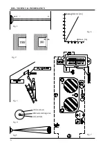
(see fig. 1)
The device has to be installed on one side of the area
to be protected just under the level of the ceiling
and the special reflector (FX/01, FX/02, FX04,
FX/05), chosen according to the required range,
on the opposite side.
We recommend to read and follow our instructions
carefully to install the detector in a correct way.
The device's excellent working results, will widely
compensate the time spent in reading these
instructions.
1 - OPERATING INSTRUCTIONS
1.1
- Unmount the detector's body from the flush
mounting box taking off the 4 screws.
1.2
- Install the flush mounting box safely inside the
wall. Be careful to allign the box border with the
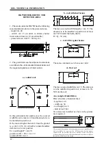
wall's surface. The border has not to be flushed into
the wall more than a few millimeters to avoid optical
problems (fig.2). The box has to be installed 30-50
cm. below the level of the ceiling.
1.3
- Put the guide tube and the cables inside the
box using the blowable holes marked on the box
to pass them through.
1.4 -
Re-mount the detector's body with the 4 screws.
1.5
- Install the FX reflector on the opposite wall at
the same height of the detector. It's not necessary that
the reflector is placed perfectly in front of the detector
(an angle difference up to 8 degrees in all directions is
allowed).
2 - WIRING
2.1
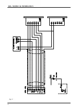
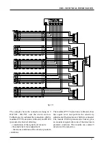
- Connection cables. The small current of the
device (14 mA with normally not powered relay
and 25 mA with normally powered relay) allows
to use small cable sections. A shielded cable (8
wires + external shield) is suggested. With this
kind of cable it’s possible to have a remote signal:
the alarm signal (COM-NA-NC terminals)
the prealarm signal (OC terminal)
the signal level remote measure (TP1 terminal)
the detector remote control terminals (sensitivity
adjustment) (TP2-TP3 terminals)
the power supply of detector (- and + terminals)
the cable shielding must be wired only on one
side (see fig. 9)
3 - ELECTRICAL CONNECTIONS
3.1
- Connect the device cables as shown on the
labels facing the terminal boards. The given
symbols indicate what follows:
OC Open Collector - prealarm output. It is
possible to connect this terminal to the optional
EV450 to have a sound signal or a led for a
optical signal (see fig.9) for the prealarm,
maximun output current = 50 mA.
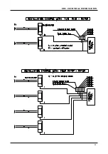
TP2-TP3. They must be connected to the
optional external accessory (EV570) for the re-
mote control of the sensitivity. Otherwise it must
be unconnected.
TP1. Test point 1. It allows to measure the
signal level.This operation is carried out
connecting the accessory STS01 on the
connector of the printed circuit (see fig. 7) or
using a voltmeter connected between TP1 and
the negative [terminal (-), ground].
COM-NA-NC. Alarm relay. The showed
connection is valid when the detector is not in
alarm condition and the JP3 jump is in position
2-3. The CO-NA-NC terminals are voltage free.
(-) (+) input terminals 12/24 Vcc. Select the right
voltage using of the jumper JP4 ( see fig. 8). The
given polarities must be respected.
Содержание RK 75 R
Страница 7: ...7 EDS TECHNICALINFORMATION Fig 8 INSIDE VIEW ...
Страница 8: ...8 EDS TECHNICALINFORMATION fig 9 ...
Страница 11: ...11 EDS TECHNICALINFORMATION ...

