EDS - TECHNICAL INSTRUCTIONS
4
REFLECTIVE TYPE
OPTICAL BEAM SMOKE
DETECTOR
RK100-R - RK100-RS
GENERAL
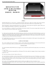
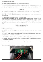
The RK100-R(S) detector is a microprocessor controlled optical beam smoke detector, that bases its working concept on the interaction
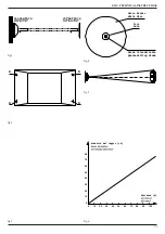
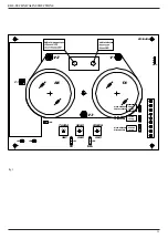
between the smoke present in a room and an infrared beam emitted by a transmitter and reflected by an optical reflector (fig.1).
The normal installation consists in mounting the detector on a wall of the room to be protected and in fixing the FX reflector (FX01, FX02,
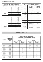
FX03, etc depending on the distance- see table in fig.7) on the opposite wall.
For a correct installation, we recommend to read and follow our instructions carefully. The excellent working results of the device will
widely compensate the time spent reading these instructions.
1 - QUALIFIED PERSONELL
1.1
- All the operations of installation, setup, startup, maintenance and verifications of operation of the The RK100-R(S) detector, must only
be performed by qualified personnell. These people are qualified for their experience, specialization courses, knowledge of the current
standards and of the technical specifications, features and usage method of the product. These people therefore are able to avoid errors
or damages and assure an optimal functioning of the product.
1.2
- The RK100R(S) detector must be used according to the tecnical data and to the information of this manual, to the installation and to
the ambiental and operational condition
2 - RELEVANT STANDARDS
2.1
- For the installation in European Community countries you must follow the EC standard EN54-14 (Fire detection and fire alarm
systems). In extraeuropean countries you must respect the relevant international and national standards.
3 - INSTALLATION
3.1
- For the installation of the RK100-R detector we suggest to also use, besides the normal tools (drill, expansion plugs, etc), the following
elements:
• 1 - 7mm “C” Key
• 1 - multimeter (we recommend an analog hand Tester or EDS analog STS-01 meter (optional) to be plugged on the special connector positioned
on detector’s circuit.
3.2
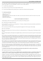
- Unscrew the 4 fixing screws (fig. 2) and remove the cover
3.3
- Install the detector at a distance from the ceiling within the 10% of the height of the room to protect. This distance can be varied by
the system designer if particular environmental conditions exist. Wall fixing must be done with care using the 4 holes provided inside the
container. If the wall is a solid masonry one, 4 expansion plugs are enough. It’s extremely important that the fixing wall or surface is rigid and
not subject to deformations.
3.4
- Pass the cables through the holes obtained breaking the suitable zones marked on the sides of the detector’s base.
It is important to use a suitable chock with a connecting pipe to avoid that the dust penetrates inside the device, possibly causing failure
to its correct functioning.

