Edge Technologies Patriot 338 Скачать руководство пользователя страница 118

PATRIOT 

338/551


112 


REV 10:2019 

Check 1st Part:

 This parameter allows the long and short feed safety values to be disabled on 

the first part after switching the bar feeder to Automatic mode or for the first part after a bar 

change. 


4.  Press the Back button to return to the previous page when finished with this page. 


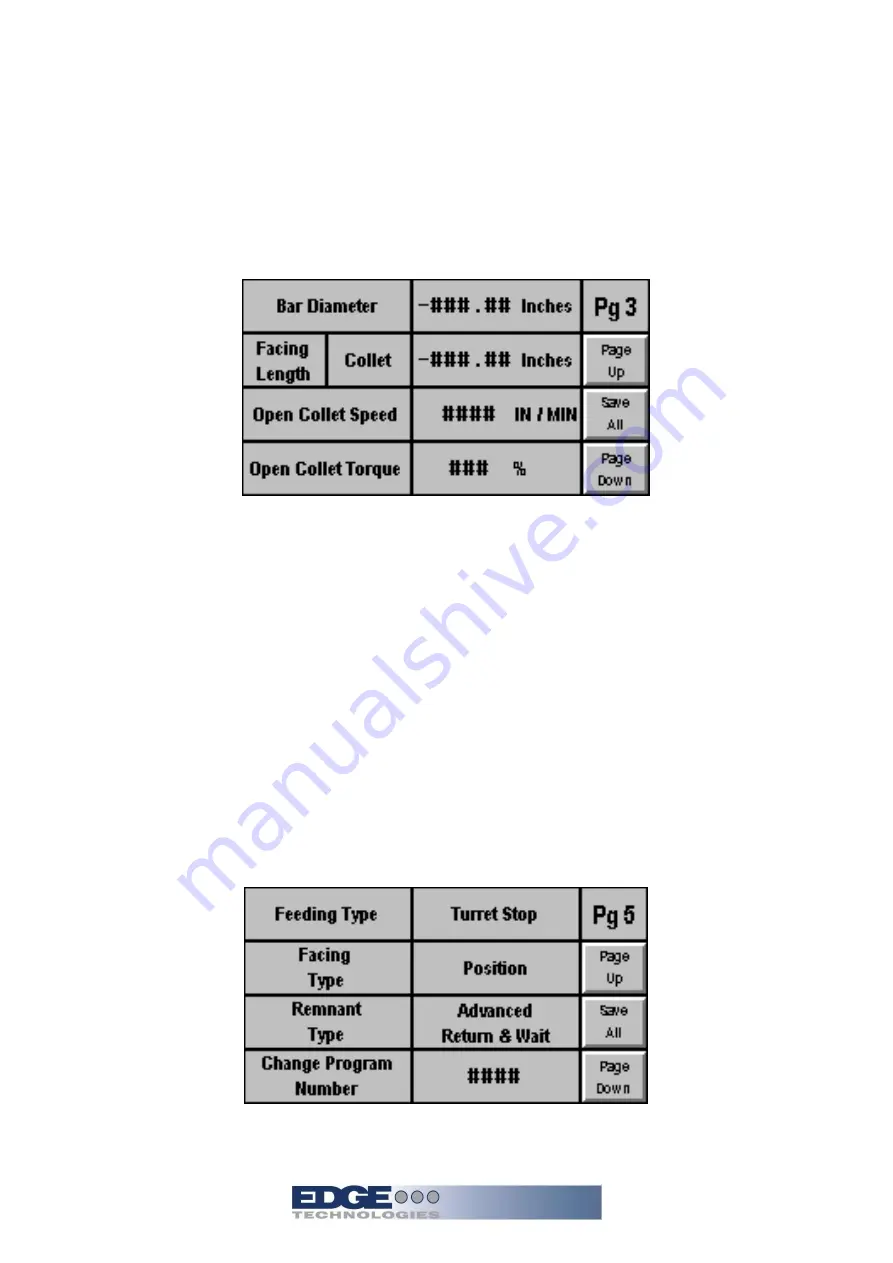
5.  Press the page down button to access parameter Page 3.


Bar Diameter: 

Enter the diameter of the bar stock to be run.    For hexagonal and square stock 

enter the diameter as measured across the points of the material. 


Facing Length: 

This parameter allows adjustment to the stopping position of the new bar at the 

completion of a bar change. See section 8 for the complete description of the parameter. 


Open Collet Speed:

 This parameter allows adjustment to the feeding speed of the bar stock in 

Automatic mode. 


Open Collet Torque:

 This parameter allows adjustment of the pushing force of the bar pusher 

in the Automatic mode. The range is plus or minus 50% of the setting selected through the Bar 

Diameter parameter.


6.  Press the Page Down button to continue.


Feeding Type Selects the method of feeding. Selections allow feeding to a hard stop on the 

lathe or feeding to a distance set by the Feedout parameters on parameter page 1.1. 

Содержание Patriot 338

Страница 1: ...Patriot 338 551 OPERATIONS MANUAL OPERATIONS MANUAL Version 10...

Страница 2: ...ssed air supply including oil 10 2 4 Safety 11 2 4 2 Covers 11 2 4 3 Lathe Door Safety 11 2 5 Emergency Stop Buttons 12 2 6 Electrical Safety 13 2 6 2 Electrical Connection 14 2 6 3 Glossary of Terms...

Страница 3: ...Movable Anti Vibration Device MAVD Adjustment 66 5 3 2 MAVD Block Sets 68 5 4 Bushing Block Device with Air Knife 69 5 5 Drip Pan Oil Management 73 5 6 Pusher Drive Chain 75 5 7 Synchronization Syste...

Страница 4: ...tion 121 Parameter Page 2 3 Option 122 Parameter Page 3 Option 123 Parameter Page 4 Option 124 Parameter Page 5 Option 125 Parameter Page 6 Option 126 Factory Parameter Page 11 127 Factory Parameter P...

Страница 5: ...larm 09 148 Alarm 10 149 Alarm 11 149 Alarm 12 151 Alarm 13 151 Alarm 14 152 Alarm 15 152 Alarm 16 153 Alarm 17 154 Alarm 20 154 Alarm 21 154 Alarm 22 155 Alarm 23 155 Alarm 24 155 Alarm 25 156 Alarm...

Страница 6: ...164 Alarm 51 165 Alarm 52 165 Resetting Emergency Stop Safety interlocks ESSI 167 Patriot Setting of the S2 and S3 Sensor Plate 168 9 Electrical Parts and Schematics Electrical Parts 10 Replacement Pa...

Страница 7: ...ry to the operator and damage to the machine as well as helping to realize the maximum potential of the bar feeder unloader and machine tool Particularly important points of information are preceded b...

Страница 8: ...d harmless Edge Technologies from any and all claims or liabilities from accidents involving these machines caused by failure of users his employees or agents to follow instructions warnings or recomm...

Страница 9: ...d Current J Power K Short Circuit Rating L Wiring Drawing Number Important information When inquiring about or ordering parts please have the machine model type and serial number on hand Refer to the...

Страница 10: ...steady the material and control vibration The end of the bar stock is supported by a bearing unit on the end of the bar pusher and the work holding system of the lathe An anti vibration device is loc...

Страница 11: ...bar stock collet to be chosen by customer specific collet needed for each stock diameter 1 Bushing block for outboard anti vibration device to be chosen by customer based on bar diameter Automatic rem...

Страница 12: ...sformers On certain lathes a Chucker Mode option is available This option requires the physical movement of the bar feeder fore and aft to the lathe headstock Z axis movement plane while anchored to t...

Страница 13: ...nd the rear of the machine as shown in the diagram below Other necessities are suitable lighting and a compressed air supply The bar feeder is not suitable for and cannot be adapted to use in an explo...

Страница 14: ...ations and Capacities 2 3 2 Bar Feeder Oil Requirements Oil Viscosity Brand Description ISO 100 BP Energol CS 100 Castrol Magna 100 Chevron Circulating Oil 100 Elf Movixa 100 Esso Nuto 100 Mobil Vectr...

Страница 15: ...5mm 12 7mm 500 32mm 1 260 35mm 1 377 38mm 37 0mm 15 8mm 625 33 3mm 1 312 37mm 1 456 Channel sizes below can be used ONLY with the Patriot 551 39mm 38 0mm 15 8mm 625 33 3mm 1 312 38mm 1 500 43mm 42 5mm...

Страница 16: ...e air supply tube into A Pull up and rotate knob counter clockwise B and set the pressure at 6kg cm2 71 11 99 56 PSI Air system Lubricant Viscosity of 32 temperature 40 ISO VG type Oil level should be...

Страница 17: ...should always be in place during bar feeder operation The Patriot is supplied with covers to prevent access to moving parts during operation The hood of the machine is equipped with a safety switch to...

Страница 18: ...placed into emergency stop condition from the machine control panel The lathe emergency stop system will place the bar feeder into emergency stop as well During installation on some lathes during emer...

Страница 19: ...lathe is verified with a voltmeter at the power supply connector Verify this voltage matches the required voltage of the bar feeder see machine operator manual section 2 3 Specifications and Capaciti...

Страница 20: ...machine plug and cables will be supplied This supplied harness must be wired into the lathe electrical cabinet by a qualified technician The lathe must support a machine type interface for the machin...

Страница 21: ...termined the current bar is too short to produce anymore parts Bar feeder on Typically a normally open circuit controlled by the bar feeder alarm relay Voltage is supplied by the lathe Lathe Emergency...

Страница 22: ...ly then signals from the bar feeder will not work correctly First check to see if the interface is turned ON in the lathe settings Always check the lathe manual to see if there is correct documentatio...

Страница 23: ...otating spindle To correct the automatic signal on Edge products a wire may need to be moved in a terminal block The FMB products require moving a wire on a relay specified for the bar feeder automati...

Страница 24: ...wiring in the lathe There are some lathes that do not supply emergency stop to the bar feeder If possible try to find a way to wire the emergency stop using the lathe information Bar feeder common Th...

Страница 25: ...If these are correct then ensure that the lathe bar change relay is on when the M code is latched in the program Some lathe controls need to have keep relays turned on or off depending on how signals...

Страница 26: ...eder should not be able to feed forward This can also be used like a feed stop depending on the lathe and bar feeder If the door safety is used but not satisfied some bar feeders will not feed Other b...

Страница 27: ...eeder voltage to the correct location in the plug If the voltage is too high or varies too much on the lathe the customer may need to have an electrician come out The may also be a need for a transfor...

Страница 28: ...der Lifting and moving the bar feeder by forklift is the preferred method of handling the machine The machine should be moved only by personnel qualified in the operation of forklifts The forks must e...

Страница 29: ...ngth 1M under the bar feeder outside of the stands using suitable lifting straps hoist the bar feeder Hoisting with bar feeder on pallet Using suitable lifting straps positioned under the pallet near...

Страница 30: ...nual alingment procedure Lathe must be operational to perform the alingment and installation with the proper chucking package On some lathe models there are covers for the spindle area These covers ma...

Страница 31: ...ituation hopefully even before the customer is exposed to the trouble area The main goal of the preliminary inspection is to minimize delays in the completion or the necessary postponement of the inst...

Страница 32: ...able and correct according to the customer s pick ticket in the bar feeder Spindle liners Check that I D matches pusher test fit in the lathe verify that the retaining ring is available and functional...

Страница 33: ...Lathe under power and leveled Electrical interface available and installed Don t forget to double check the AC supplied voltage and pins location prior to plug in Chucking package available and insta...

Страница 34: ...ired bar feed level pads and associated nuts washers and screws b Anchor bolts c Head stock adaptors d Correct channel set installed e Threaded rod bracket and nuts f Telescoping or hard nose g Hardno...

Страница 35: ...required b Align as required c Cut telescoping or hardnose nose as required i Verify collapsibility of telescoping nose ii Verify Reach of telescoping nose 11 Connect synchronization rod a Cut threade...

Страница 36: ...in over travel condition nearest the guide bushing Please refer to the diagram and chart below for the correct dimension for bar feeder placement The bar feeder is available in two pusher length conf...

Страница 37: ...cations To finish off the stand system 4 metal level pads with adjusting arbors are installed to the 4 last stand locations Axial shift equipped machines may have the arrangement of level pad location...

Страница 38: ...cate and clean all the leveling pad components with a rag A heavy amount of anti corrosion lube is applied to keep parts fresh 4 x Leveling pad 4 x Threaded rod with 2 washer and 2 nuts 4 x Arbor with...

Страница 39: ...level the bar feeder 7 Determine the distance from the floor to the center of the spindle of the lathe Compare this dimension to the distance from the bottom of the bar feeder stand to the center of...

Страница 40: ...the ejector block is made Do this for all 4 level pads 12 Raise the bar feeder so the weight is now on the 4 leveling pads and ejector blocks Be sure the bar feeder is level 12 Insert a thread rod int...

Страница 41: ...moving the pusher with the pendant when the hood is disabled Note As alignment is adjusted make verify distance from bar feeder to lathe does not change String Alignment Procedure Not supplied is the...

Страница 42: ...roper plug size for lathe the collet insert and close lathe collet move lathe Z axis to Z over travel pull the nylon string tight and secure in place Directional adjustment Move the bar feeder so that...

Страница 43: ...target center Use the arbor screw to adjust the height and tilt of the bar feeder If the distance between the base of the stand and the floor exceeds 4 inches a stand height adjustment will need to be...

Страница 44: ...y 5 Lock lower threaded rod nut 6 Lock upper threaded rod nut 7 Once the nuts have been locked verify the alignment 8 The supporting level pads are to be set to assist in the overall support of the ma...

Страница 45: ...elow is a non axial shift Patriot foot pad configuration Leveling pads 1 and 2 may be swapped position on axial track equipped machines for more efficient aligning 1 Level pads positioned at outer loc...

Страница 46: ...emoved from the lathe the head stock will then be positioned in place of the guide bushing The distance of headstock movement forward into chucker mode will be the amount of bar feeder movement requir...

Страница 47: ...ed a lever is used for lifting A small pin tethered to the cabinet is used to hold the lever in place when the Patriot is lifted No maintenance of the bearing is required They are sealed for life Warn...

Страница 48: ...eeder movement and head stock movement during the Swiss and Chucker change Bar feeder is anchored down to floor and equipped with axial shift option Bar feeder shifted into chucker position Guide bush...

Страница 49: ...aws to the face of the lathe collet are the typical measurement points The telescoping nose must be short enough to collapse without bottoming out and extend without over extending The synchronization...

Страница 50: ...ch distance Bar feeder material loading position Position Movement length 1 120mm 2 160mm 3 230mm When position 2 is to be used remove screw from position 1 and place it into hole position 2 The axial...

Страница 51: ...critical during the installation The switch locations are preinstalled and do not require adjusting The adjustment will come from the positioning of the switch plate and trimming the plate as required...

Страница 52: ...PATRIOT 338 551 46 REV 10 2019...

Страница 53: ...isconnect bar feed synchronous rod and telescoping nose from lathe head stock at the MAVD 7 From the side of stand cabinets remove 2 axial track locking bolts from both stands 8 Rotate both axial shif...

Страница 54: ...cabinets remove 2 axial track locking bolts from both stands 7 Rotate both axial shift levers to raise bar feed 8 Push bar feed rearward to the Swiss position 9 Rotate both axial shift levers to lowe...

Страница 55: ...machine alarms can be produced or excessive remnants will be observed During initial setup it is required to measure and record the following Parameters Max end of bar menu page 11 Facing distance men...

Страница 56: ...PATRIOT 338 551 50 REV 10 2019...

Страница 57: ...the bushing block mounting flange There are nuts on the screws as well The back sheet metal cover will require lowering to access the nuts on the right side of the bushing block device The 4 jack scre...

Страница 58: ...ded hand crank This is helpful when performing a channel changeover of the bar feeder The sheet metal of the Patriot is equipped with an access hole to allow for insertion of the hand crank Insert han...

Страница 59: ...pads to the floor It is recommended to drill the holes for the anchor bolts completely through the floor if possible or at least as deep as the anchor bolt is long so that the bolt may be driven flush...

Страница 60: ...there is a spacing ring that is required for the nose to be fastened to the MAVD Movable anti vibration Device MAVD Used only on Swiss type lathes The MAVD is fixed at the end of the spindle of the la...

Страница 61: ...of the long pusher the lathe spindle normally requires a spindle liner This liner reduces the inner diameter of the spindle to the diameter of the pusher The liner diameter should be approximately 2m...

Страница 62: ...is a spacing ring A that is required for the nose to be fastened to the MAVD Note when cutting the nose it is very important the surface is perpendicular to the shaft The telescoping nose is matched...

Страница 63: ...taining bracket is one size fits all Warning machine damage may occur if telescoping nose is not properly connected to lathe headstock Be sure the retaining ring and plate all fit flush and completely...

Страница 64: ...hering device is then attached to the end of the nose for ejected oil to gather and return to the with a drain hose to the bar feeder The hardnose must be cut slightly shorter to allow for the install...

Страница 65: ...e by 2 screws and lock nuts There is about 2 inches of insertion avaiable of the hard nose This is used to close up any gap between the lathe sheet metal and attaching seal 1 Flange 2 Hardnose insert...

Страница 66: ...led into bar feeder and lathe MAVD equipped with rollers in good condition no chunked different diameter or gouged rollers may be used It is preferred to have new rollers available for alignment purpo...

Страница 67: ...D air cylinder This will allow the MAVD to close on the pusher when air is reconnected The air cylinder supply lines on top of the MAVD will be swapped only for adjusting and centering of the MAVD Thi...

Страница 68: ...ng screws 16 Tighten the MAVD adjustment screw so the rollers are no longer contacting the pusher 17 Remove air supply from bar feeder 18 Reverse MAVD cylinder air lines to original positions 19 Attac...

Страница 69: ...PATRIOT 338 551 63 REV 10 2019 5 Systems and Adjustments 5 1 Bar feeder Component Locations...

Страница 70: ...g magazine 2 Remove any material from the magazine 3 Loosen the locking lever for the support plate 1 and lift the plate to the highest position 4 Place one bar to be loaded on the magazine 5 Rotate t...

Страница 71: ...2 Support plate Adjustment Screw The vertical adjustment plate moves as the adjustment point The material lifter is stationary and bar center should be just past the edge of the lifter 1 2 Lifter wil...

Страница 72: ...first time make sure the Movable Anti Vibration Device rollers are open Roller damage may occur when material or pusher is moved into the rollers 1 Load a bar using the bar feeder into the lathe and...

Страница 73: ...Adjust as required The MAVD will include an open stop screw If this screw is screwed in too far this will keep the MAVD from opening fully This could damage the rollers if larger material is loaded wi...

Страница 74: ...ptimizing the bar feeder performance with certain material shapes and operating speeds 2 Blocks of the same size are required for each MAVD Choose a block size that is 2mm larger than your working dia...

Страница 75: ...p The Patriot is equipped with a unique bushing block device providing material support upon discharge from the channel Bar feeder oil is supplied to the device which adds to the vibration management...

Страница 76: ...he bypass switch attached to the upper portion of the bushing block device Bypass switch Note Bushing blocks have been removed Bushing blocks will only fit one direction into device and are symmetrica...

Страница 77: ...PATRIOT 338 551 71 REV 10 2019 Valve full closed the handle is in line with the valve valve is closed in image Valve full open is 90 degrees from valve...

Страница 78: ...g the nose The air control valve is energized when the pusher moves forward The air flow is adjustable via a thumb wheel on the valve Note The air knife is a standard feature on the Swiss equipped Pat...

Страница 79: ...e end of the fixed nose When the air knife and oil flow is set correctly minimal oil migration to the lathe is substantially limited Directing the oil with a drain pan is limited to the stroke of the...

Страница 80: ...4 REV 10 2019 Hardnose oil collector The oil collector on the hard nose is plumbed to allow oil flow back to the bar feeder If flow is too high the bushing block devise oiler valve should be adjusted...

Страница 81: ...elow 1 Place bar feeder and lathe into emergency stop 2 Material may need to be removed form channel if the pusher cannot be moved without obstruction 3 Open bar feeder hood 4 On older Patriot models...

Страница 82: ...ns Operation For installations on sliding headstock lathes a synchronization device may be used A rod is linked to the moveable anti vibration device mounted to the lathe spindle This rod passes throu...

Страница 83: ...erclockwise to loosen the belt 6 Adjust belt tension to no more than 10mm of deflection Do not over tighten the belt Premature failure of the belt may occur 7 Once the adjustment has been made secure...

Страница 84: ...may result Warning all channel sections must be in position prior to operation Machine damage will occur if channel sections are not in the proper position The channel set on the Patriot may be change...

Страница 85: ...pecific to a region within the channel rail It is recommended that 1 channel section at a time is removed and replaced with the conversion piece All components with in a channel set is specific to the...

Страница 86: ...nant tray empty Correct guide channels installed Correct pusher size and corresponding guide channel installed Install corresponding lathe spindle liner Adjust roller steady Only if roller steady used...

Страница 87: ...area between the mating surfaces of the screw This will act as a locking mechanism especially if the 2 surfaces were clean of any oils It is extremely important the screws and threads have been cleane...

Страница 88: ...h a pin securement is available from Edge Technologies as well Refer to parts section for part numbers and available sizes The rotating tip diameter should be 1mm smaller diameter than the guide chann...

Страница 89: ...y tightened Countersunk washer required for lower rearmost channel section 2 required Warning incorrect removal or installation of the channel sections will damage the retaining pin Review instruction...

Страница 90: ...Upper channel screw without oil hole Lower channel screw with oil hole lower channels must always contain the mounting screw with hole Be sure this oil passage is not clogged When installed the screw...

Страница 91: ...er location To reset the cutting Sensor flap back to measuring positon a small throttle valve is used to push the flap back into position This valve is air controlled by the PLC The resetting of this...

Страница 92: ...PATRIOT 338 551 86 REV 10 2019 Channel set has been removed...

Страница 93: ...terial is placed farther from the gripper the correct amount of material will not be inside the bar feeder collet This may lead to material and bar feeder collet separation Thus causing additional iss...

Страница 94: ...PATRIOT 338 551 88 REV 10 2019 The gripper assembly is designed to function with out any adjustments...

Страница 95: ...tion step The movement between extraction and introduction should always be fluid with the servo drive motor The air cylinder piston shaft is attached to the balance block The balance block contains a...

Страница 96: ...m this position back The chain guide removed from bar feeder The finger will move under the chain guide at the point below as it moves forward In the reverse the finger will engage the carriage pocket...

Страница 97: ...not connected to the carriage for image purpose When the balance block is moved back the finger will slide up in the opening and engage the carriage pocket There are no adjustments to the balance bloc...

Страница 98: ...hed to the balance block will be positioned Underside of Carriage On the top side of the carriage the pre feed pusher is screwed in while the long pusher flag sits into a machined pocket It is very im...

Страница 99: ...f the lock mechanism Channel is open and unlocked channel is removed Channel lock unlock cylinder The 8ft Patriot does not use the lock linkage The channel open close cylinder is used to hold the chan...

Страница 100: ...within the lathe spindle while turning it may prevent loading if bar condition is such that the bar collides with the back of the lathe spindle or it binds while feeding into the spindle Bars of small...

Страница 101: ...dicator readings at each location 3 Calculate both the tolerance for each meter increment and also the tolerance over the entire length of bar Compare the recorded values to the required tolerances to...

Страница 102: ...p versus flats up Chamfers on the lathe end of the bar are not usually required only an edge break to ensure no burrs remain to snag on the lathe collet RPM Limiting Factors Certain conditions may lim...

Страница 103: ...PATRIOT 338 551 97 REV 10 2019 5 18 Vibration Troubleshooting Check List...

Страница 104: ...commands directly through the touch screen There are many obvious defined buttons or keys when pressed an action of some type appears on screen There are undefined buttons or keys when a value or desc...

Страница 105: ...ual retreat Left 6 Origin point light Left 7 Chuck open light 8 Allow feeding on 9 Manual mode 10 Manual mode light 11 Manual Gripping in out 12 Pusher extracted 13 Manual channel open close 14 Channe...

Страница 106: ...tton or the bar feeder will not change to Automatic To Power Up After An Alarm 1 Check the alarm message there will be details about the alarm 2 Clear the cause of the alarm 3 Press the green start bu...

Страница 107: ...plete understanding of machine operation is required 6 4 3 Automatic work operation While and the light are on press and start to work automatically Or while and guiding light off and either or is on...

Страница 108: ...ken stick to trip the cutting sensor flag Caution when the hood switch has been by passed during the re zero procedure using the Bar Off feature Warning this procedure requires access to the factory p...

Страница 109: ...tely stopped moving release the gripper button and the zero reference will be complete At this point all issues regarding the loss of the home position should be gone and the barfeeder will be ready f...

Страница 110: ...erial The LED on the button will light when the carriage is pulled back to the rear limit 4 Press the Grippers button to open the grippers 5 Press the Channel Open Close button to open the guide chann...

Страница 111: ...tower light Status conditions below Red light is on bar feeder is in emergency stop Green light is on bar feeder is in machining mode Green light is flashing bar feeder is in bar change operation The...

Страница 112: ...y of the remaining material that can be machined The unit of measurement may be toggled between metric and inch by touching the value on the screen 5 The next line has information areas to indicate th...

Страница 113: ...screens 2 The top line shows the bar feeder mode status and the current program number 3 The next line shows the position of the bar feeder from the zero position 4 Below the pusher position is the st...

Страница 114: ...close on the bar if present there need not be a bar in the channel at this step 4 The pusher will retract and the channel will open 5 A new bar will fall into the guide channel 6 The pre feed pusher w...

Страница 115: ...AR OFF 2 The bar pusher will retract to the home position 3 The grippers will close on the bar and the pusher will pull off the material 4 The grippers will open 5 The channel may then be opened with...

Страница 116: ...eeder with only a few steps Should the memory become full an individual job may be deleted to make room for the next or an existing job can be easily altered A template is made in the bar feeder durin...

Страница 117: ...nter the same value as Part Length 1 If using more than one feedout per part enter only the distance of the first feedout on this page and the other feedout distances on the appropriate parameter page...

Страница 118: ...e material Facing Length This parameter allows adjustment to the stopping position of the new bar at the completion of a bar change See section 8 for the complete description of the parameter Open Col...

Страница 119: ...e number of the current program 7 Press the Page down Button to continue This page allows control of the Moveable Anti Vibration Device Move the pusher just before the MAVD rollers Note the distance r...

Страница 120: ...PATRIOT 338 551 114 REV 10 2019 Press the LOAD button to initialize the program Press the EDIT button to make changes to the existing program then press Save All to store the changes...

Страница 121: ...e feedouts per part Parameter is disabled if set to zero Press the Feedout 1 1 dimension button to access page 1 1 and additional options Feedout 1 2 Used when making multiple feed outs per part Feedo...

Страница 122: ...collet opens On fixed headstock lathes the pusher must advance at least this distance before the lathe collet closes The parameter is disabled if set to zero Long Feed Safety Sets maximum distance pu...

Страница 123: ...llet opens On fixed headstock lathes the pusher must advance at least this distance before the lathe collet closes The parameter is disabled if set to zero Long Feed Safety Sets maximum distance pushe...

Страница 124: ...llet opens On fixed headstock lathes the pusher must advance at least this distance before the lathe collet closes The parameter is disabled if set to zero Long Feed Safety Sets maximum distance pushe...

Страница 125: ...sed when making multiple feed outs per part Feedout 2 1 is the first of 3 possible feedouts per part Parameter is disabled if set to zero Press the Feedout 2 1 dimension button to access page 2 1 and...

Страница 126: ...his distance before the lathe collet opens On fixed headstock lathes the pusher must advance at least this distance before the lathe collet closes The parameter is disabled if set to zero Long Feed Sa...

Страница 127: ...s distance before the lathe collet opens On fixed headstock lathes the pusher must advance at least this distance before the lathe collet closes The parameter is disabled if set to zero Long Feed Safe...

Страница 128: ...s distance before the lathe collet opens On fixed headstock lathes the pusher must advance at least this distance before the lathe collet closes The parameter is disabled if set to zero Long Feed Safe...

Страница 129: ...g point of the material to be loaded Collet Chuck There are two options for the facing length setting Pressing the Collet Chuck button toggles between the two options This feature allows for two diffe...

Страница 130: ...e collet to be closed when the bar feeder is in automatic for up to the number of seconds set in this parameter If the length of time is exceeded an alarm is generated The parameter is disabled if set...

Страница 131: ...s of remnant disposal Extraction The material is held in a finger collet The remnant is returned with the bar pusher the grippers close on the remnant and the pusher pulls the collet off the bar end T...

Страница 132: ...m closing on the bar pusher after it has opened to allow the bar pusher collet to pass through MAVD Opening Position Sets the position for the moveable anti vibration device open MAVD Open Close With...

Страница 133: ...Collet Fixed headstock lathes Distance from the measuring flag front gate at the end of the guide channel to the face of the lathe collet Sliding headstock lathe Distance from the measuring flag front...

Страница 134: ...er Oil Pump Shutoff Distance Sets the position from zero for the oil pump to turn off MAVD Opening Position Sets the position from zero that the movable anti vibration device opens to allow the bar pu...

Страница 135: ...ration Device also called the fixed steady roller Position should be set 1 2 inches before the pusher collet reaches the steady roller unit 2nd Anti Vibration Opening Position Not used on the Patriot...

Страница 136: ...ation set in parameter End Of Bar Pulse on page 16 Feed Confirm Signal Type Selects between different modes of generating a confirmation signal for bar pushing Choices are Not Used No signal is output...

Страница 137: ...sent Impulse On Time Sets a length of time for the bar feeder to send a signal to the lathe to rotate the spindle during bar change This parameter works with Impulse Off Time Default is 0 deactivatin...

Страница 138: ...the end of bar signal is set to pulse Feed Confirm Pulse Sets the length of time in seconds for the signal to remain on when the feed confirmation signal is set to pulse Cycle Start Pulse Sets the le...

Страница 139: ...oor Open signal from the lathe as either a normally open or normally closed signal Lathe Alarm Allows the bar feeder to accept the Lathe Alarm signal from the lathe as either a normally open or normal...

Страница 140: ...Of Bar Test button to check the operation of the output for End Of Bar Pressing the button will turn on output Y27 and relay R4 Y30 Test button to check the operation of output Y30 and relay R5 Y30 c...

Страница 141: ...y Provides visual aid to check the signal Lathe Door Safety from the lathe Button highlights when the signal is active Input X37 will also be on Lathe Alarm Provides visual aid to check the signal Lat...

Страница 142: ...Default password is 0 User Load Program Password Sets a password to be required before access to load a new barfeeder program is allowed Default password is 0 User Edit Program Password Sets a passwor...

Страница 143: ...n set to ON User Page 5 Allows User Page 5 to be seen and accessed in User parameters when set to ON User Page 6 Allows User Page 6 to be seen and accessed in User parameters when set to ON Initial Us...

Страница 144: ...Speed 1 Speed of the pre feed pusher as it advances until it reaches the slowdown position 1st Feed Speed 2 Speed of the pre feed pusher in the slow down position as it approaches facing position Thi...

Страница 145: ...acing Speed 2 Forward speed of the bar pusher during the distance specified in the Facing Speed Slowdown Distance Parameter Facing Speed Slowdown Distance Distance for the facing speed 2 and peck cycl...

Страница 146: ...ed by the clutch when moving the bar pusher forward in manual mode via the jog buttons or through the input for Manual Forward Manual Reverse Speed Speed of the pusher and pre feed pusher in reverse w...

Страница 147: ...when the lathe collet is closed Collet Close Torque Sets the pushing force for the bar pusher when the bar feeder is in automatic mode and the lathe collet is closed 1st Anti vibration Closing When s...

Страница 148: ...meter Page 26 Pusher Back Off Tolerance Sets an allowable distance for the bar pusher to move backward when the bar feeder is in automatic and the lathe collet is open If the pusher moves backward in...

Страница 149: ...olvents may damage plastic components Dust and or wipe down the bar feeder with a mild cleaner daily Component Action Frequency Hours Regular Period 200 1250 2500 200 1250 Collet Check wear Guide chan...

Страница 150: ...s Cracks Oil level ok Secure mounting Proper air regulation is set Repair any issues above 7 1 4 Pneumatic System Lubrication The pneumatic systems incorporates a self oiling system into the air regul...

Страница 151: ...In emergency Restart The bar feeder is reset but the bar feeder can t auto to start The lathe is sending signal Check the connection Air devices are not functioning Compressed air is not present Check...

Страница 152: ...un Stop switch to the back of the control panel rectangular 9 pin plug connected to the COM 2 port Release E Stop on Lathe Make sure lathe is not in an alarm other than a bar feeder alarm Release E St...

Страница 153: ...t is open when the bar feeder is in automatic Inverter Alarm Reset lathe e stop Reset lathe alarm Check wiring on interface Check for continuity between the wires for Emergency From Lathe if used chec...

Страница 154: ...eck Air Pressure Switch Pressure is correct when red light is on Check input at PLC X23 The X23 LED will be on when the signal from the switch indicates proper air pressure Reset Overload The overload...

Страница 155: ...nd observe the output to make sure it turns on when commanding the shuttle to pull backward Check collet ID size is correct size Check the collapsed ID of the collet Check for minimum chamfer of 3mm o...

Страница 156: ...inder to the shuttle mechanism Pusher not at home position Re zero the bar pusher Not enough air pressure to lift channel Check the air pressure gauge Increase pressure with the regulator if necessary...

Страница 157: ...on PLC X7 Flag stuck in down position Manually operate the measuring flag Check for debris impeding the operation of the flag Check the flag for damage Material impeding flag movement Remove the mate...

Страница 158: ...on and off Check input on PLC X2 Move the bar pusher back and forth under the home proximity sensor and watch for the input X2 to turn on and off Adjust max feed parameter position Verify the positio...

Страница 159: ...oximity switch and check that the LED lights check input X2 it should light when the proximity switch lights Rezero barfeed Start with the guide channel closed and the pusher forward about 12 inches P...

Страница 160: ...hts check input X2 it should light when the proximity switch lights Rezero barfeed Start with the guide channel closed and the pusher forward about 12 inches Press and hold the forward and reverse but...

Страница 161: ...b parameters for correct settings Part length should equal the actual part length cutoff tool width facing stock Feed out sub parameters combined should equal the part length setting Check for remnant...

Страница 162: ...the collet open signal Check input on PLC X23 The input should toggle on and off with the opening and closing of the lathe collet Check signal for collet close Verify that the lathe collet is not clo...

Страница 163: ...the spindle revolution during the bar change the lathe must have a provision for this signal Flashing or burrs on bar The front of the bar must be at least burr free and should have a small chamfer S...

Страница 164: ...ar change Some lathes must be left in cycle to maintain the automatic signal Turn of the single block mode and leave the lathe door closed during bar change Material feed out shorter than setting in p...

Страница 165: ...an setting in parameter Check open collet torque setting Check lathe collet spindle for debris Check for impedance to the bar pusher Set short feed value shorter than feed out needed for part The valu...

Страница 166: ...d out longer that setting in parameter Tighten the pusher drive chain Verify the pusher collet is fully seated on the material Set long feed value longer than feed out for part The value should be set...

Страница 167: ...an setting in parameter Check open collet torque setting Check lathe collet spindle for debris Check for impedance to the bar pusher Set short feed value shorter than feed out needed for part The valu...

Страница 168: ...ten the pusher drive chain Verify the pusher collet is fully seated on the material Set long feed value longer than feed out for part The value should be set at least 1mm longer than the part feed out...

Страница 169: ...eed may be too slow to accomplish the return within the allotted time Check zero sensor Verify operation of the sensor by observing the LED on switch PS2 and input X2 Check input X2 X2 should light wh...

Страница 170: ...nge begins Check operation and adjustment of the bar separators If the separators are not properly adjusted the bar stock may not fall into the channel Check the measuring switch The switch is on the...

Страница 171: ...ch for zero and then stop Check S2 switch is on Verify that the LED of the PS2 switch is on when the pusher reaches the home position and that input X2 is on when the LED of PS2 is on Check S3 switch...

Страница 172: ...PATRIOT 338 551 166 REV 10 2019...

Страница 173: ...s mode and operator attempts to move head stock into Chucker mode This will cause the Emergency Stop Safety to engage on the sync rod assembly 1 Identify the current bar feed and lathe mode of operati...

Страница 174: ...air from lathe and bar feeder prior to setting or checking the S2 and S3 sensor plate A nominal value to use when setting the plate is 52 75mm from the vertical bar feeder plate to the rear edge Spac...

Страница 175: ...1 Part Length 1 mm in Feedout 1 1 mm in Feedout 1 2 mm in Feedout 1 3 mm in Pg 1 1 Feedout 1 1 mm in Short Feed Safety mm in Long Feed Safety mm in Check 1st Part Yes No Pg 1 2 Feedout 1 2 mm in Short...

Страница 176: ...sh Delay sec0 10 Pg 5 Feeding Type Turret Stop Facing Type Position Turret Stop Remnant Type Extraction Ejection Advanced Return Wait Change Program Number Pg 6 MAVD Open Close with lathe collet OFF P...

Страница 177: ...h Metric Metric Inch Pg 15 Bar Change Return Delay sec 0 10 Cycle Start Delay sec0 10 Impulse On Time sec0 10 Impulse Off Time sec0 10 Pg 16 End of Bar Pulse sec0 10 Feed Confirm Pulse sec0 10 Cycle S...

Страница 178: ...Change Return Speed mm s in m 1st Feed Speed 1 ___ mm s in m 1st Feed Speed 2 ___ mm s in m 1st Feed Return Speed mm s in m Pg 23 Facing Speed 1 mm s in m Facing Speed 2 mm s in m Facing Speed Slowdo...

Страница 179: ......

Страница 180: ......

Страница 181: ......

Страница 182: ......

Страница 183: ......

Страница 184: ......

Страница 185: ......

Страница 186: ......

Страница 187: ......

Страница 188: ......

Страница 189: ......

Страница 190: ......

Страница 191: ......

Страница 192: ......

Страница 193: ......

Страница 194: ......

Страница 195: ......

Страница 196: ......

Страница 197: ......

Страница 198: ......

Страница 199: ......

Страница 200: ......

Страница 201: ......

Страница 202: ......

Страница 203: ......

Страница 204: ......

Страница 205: ......

Страница 206: ......

Страница 207: ......

Страница 208: ......

Страница 209: ......

Страница 210: ......

Страница 211: ......

Страница 212: ......

Страница 213: ......

Страница 214: ......

Страница 215: ......

Страница 216: ......

Страница 217: ......

Страница 218: ......

Страница 219: ......

Страница 220: ......

Страница 221: ......

Страница 222: ......

Страница 223: ......

Страница 224: ......

Страница 225: ......

Страница 226: ......

Страница 227: ......

Страница 228: ......

Страница 229: ......

Страница 230: ......

Страница 231: ......

Страница 232: ......

Страница 233: ......

Страница 234: ......

Страница 235: ......

Страница 236: ......

Страница 237: ......

Страница 238: ......

Страница 239: ......

Страница 240: ......

Страница 241: ......

Страница 242: ......

Страница 243: ......

Страница 244: ......

Страница 245: ......

Страница 246: ......

Страница 247: ......

Страница 248: ......

Страница 249: ......

Страница 250: ......

Страница 251: ......

Страница 252: ......

Страница 253: ......

Страница 254: ......

Страница 255: ......

Страница 256: ......

Страница 257: ......

Страница 258: ......

Страница 259: ......

Страница 260: ......

Страница 261: ......

Страница 262: ......

Страница 263: ......

Страница 264: ......

Страница 265: ......

Страница 266: ......

Страница 267: ......

Страница 268: ......

Страница 269: ......

Страница 270: ......

Страница 271: ......

Страница 272: ...subject to change without notice 11600 ADIE ROAD MARYLAND HEIGHTS MO 63043 314 692 8388 f 314 692 5152 www edgetechnologies com OPERATIONS MANUAL OPERATIONS MANUAL EDGE TECHNOLOGIES PRODUCTIVITY SOLU...

Отзывы: