background image


Quick Installation Guide 

ECW5211-L 

ENGLISH 


2. Connect ECW5211-L to the wired network. 

Connect the Eth1/PoE port of the AP to a switch in the existing wired LAN network with an Ethernet cable. 


3. Power on ECW5211-L. 

There are two ways to supply power over to ECW5211-L. 

a) Connect an IEEE 802.3af-compliant PSE device (e.g. a PoE switch) to the Eth1/PoE port of the AP with an 

Ethernet cable. 

b) Connect the 12V/1A power adapter to the DC power jack. 


Using a different power adapter may damage this system. 


To verify the wired connection between ECW5211-L and you switch / router, please also check 

the LED indicator of the respective network devices. 

Содержание ECW5211-L

Страница 1: ...ECW5211 L Enterprise Access Point Quick Installation Guide ...

Страница 2: ...eproduce distribute publish display perform or modify any part of this publication in any form or by any means without prior written permission from Edgecore Networks Corporation You may not alter or remove any copyright or other notice from copies of the content All other brand and product names are claimed or registered marks of their respective companies or organizations All rights reserved ...

Страница 3: ...lt the dealer or an experienced radio TV technician for help Any changes or modifications not expressly approved by the party responsible for compliance could void the user s authority to operate this equipment This device complies with Part 15 of the FCC Rules Operation is subject to the following two conditions 1 This device may not cause harmful interference and 2 this device must accept any in...

Страница 4: ...28 V2 1 1 EN 301 893 V2 1 1 EMC EN 301 489 1 V2 1 1 EN 301 489 17 V3 1 1 EMC EN 55032 2015 AC 2016 Class B EN 55024 2010 A1 2015 including the followings EN 61000 4 2 EN 61000 4 3 EN 61000 4 4 EN 61000 4 5 EN 61000 4 6 EN 61000 4 8 EN 61000 4 11 Safety EN 60950 1 2006 A11 2009 A1 2010 A12 2011 A2 2013 Caution This declaration is only valid for configurations combinations of software firmware and h...

Страница 5: ...許可 公司 商號或使用者均不得擅自變更頻率 加大功率或變更原設計之特性及功能 第十四條 低功率射頻電機之使用不得影響飛航安全及干擾合法通信 經發現有干擾現象時 應立即 停用 並改善至無干擾時方得繼續使用 前項合法通信 指依電信法規定作業之無線電通 信 低功率射頻電機須忍受合法通信或工業 科學及醫療用電波輻射性電機設備之干擾 在 5 25 5 35 秭赫頻帶內操作之無線資訊傳輸設備 限於室內使用 For UNII 產品 5GHz WLAN WIFI 警語內容 使用此產品時應避免影響附近雷達系統之操作 MPE 警語 電磁波曝露量 MPE 標準值 1mW cm2 本產品使用時建議應距離人體 28cm 減少電磁波影響 請妥適使用 ...

Страница 6: ...n Guide provides instructions on how to install the ECW5211 L and to get the network up and running with basic configurations 1 ECW5211 L x 1 2 Quick Installation Guide x 1 3 Cell Mounting Kit x 2 4 Wall Mount Screw Set x 1 5 Cushion x 4 6 Power Adapter 12V x 1 It is recommended to keep the original packing material for possible future shipment when repair or maintenance is required Any returned p...

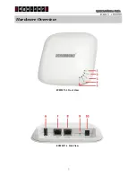
Страница 7: ...Quick Installation Guide ECW5211 L ENGLISH Hardware Overview ECW5211 L Front View ECW5211 L Side View ...

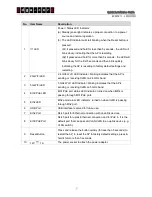
Страница 8: ...eiving traffic on 2 4 GHz band 3 5G WiFi LED 5 GHz Wi Fi LED Indicator blinking indicates that the AP is sending or receiving traffic on 5 GHz band 4 Eth1 PoE LED Eth1 PoE port status LED Indicator turned on when traffic is passing through Eth1 PoE port 5 Eth2 LED Eth2 port status LED Indicator turned on when traffic is passing through Eth2 port 6 USB Port USB interface reserved for future use 7 E...

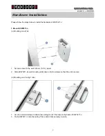
Страница 9: ...a Mounting on a Wall 1 Set two screws in the wall 128 mm 5 0 in apart 2 Slide ECW5211 L s wall mounting slots down onto the screws so that the unit is secure b Mounting on a Ceiling T Bar 1 Use the included screws to attach two ceiling mount T bar clips to the back of ECW5211 L 2 Push ECW5211 L onto the ceiling T bar until it clicks securely in place ...

Страница 10: ... are two ways to supply power over to ECW5211 L a Connect an IEEE 802 3af compliant PSE device e g a PoE switch to the Eth1 PoE port of the AP with an Ethernet cable b Connect the 12V 1A power adapter to the DC power jack Using a different power adapter may damage this system To verify the wired connection between ECW5211 L and you switch router please also check the LED indicator of the respectiv...

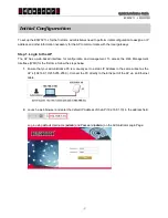
Страница 11: ...erface for configuration and management To access the Web Management Interface WMI for the first time follow the steps below 1 Ensure that your administrative PC is manually set to a static IP Address in the same subnet as the AP s 192 168 1 0 255 255 255 0 Connect the PC directly to the Eth2 port of the AP via an Ethernet cable 2 Launch a web browser and enter the default IP Address of the AP 192...

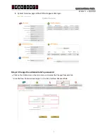
Страница 12: ...stem Overview page of the WMI will appear after login Step 2 Change the administrator s password Click on the Utilities icon on the main menu and select the Change Password tab Enter the New Password and retype it in the Re enter New Password field ...

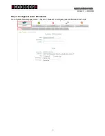
Страница 13: ...Quick Installation Guide ECW5211 L ENGLISH Step 3 Configure General Information Go to System General page Home System General to configure general information for the AP ...

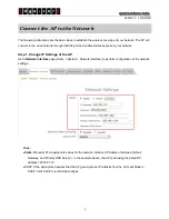
Страница 14: ... 1 Change IP Settings of the AP Go to Network Interface page Home System Network Interface to perform configuration of the network settings Mode Static Manually fill in appropriate values for the network interface IP Address Netmask Default Gateway and Primary DNS Server in the example above the AP is still using the default IP address 192 168 1 10 DHCP If the deployment requires that the AP get a...

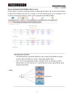
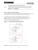
Страница 15: ...eless VAP Overview Virtual Access Point No 1 VAP 1 profile represents the first SSID available Note Virtual Access Point VAP VAP feature allows a single physical AP device with a unique single BSSID to present itself as multiple discrete APs as shown in the example diagram below Each VAP can be independently enabled or disabled with its own settings e g SSID Network Mode VLAN ID Security etc such ...

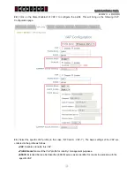
Страница 16: ...on page 2 3 Select the specific VAP profile in this case RF Card A VAP 1 The basic settings of the VAP are collected in the profile as follows VAP Disable or Enable this VAP Profile Name Name of the VAP profile for identity management purposes ESSID Extended Service Set Identifier ESSID serves as an identifier for clients to associate with the specific VAP ...

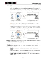
Страница 17: ...client traffic seen by the uplink gateway switch will be the IP address of the AP in this case 192 168 1 10 as shown in the diagram below VLAN ID Per SSID VLAN tagging function when enabled clients traffic which enters the AP through this SSID will be tagged with the configured VLAN ID DHCP Profile Built in DHCP Server profile IP settings of DHCP Server are under Home System DHCP Server CAPWAP Tun...

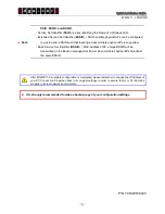
Страница 18: ...below RF Card A 2 4 GHZ 802 11g 802 11n Antenna Mode 2T2R Channel Width 40 MHz Channel 6 RF Card B 5 GHz 802 11ac Antenna Mode 2T2R Channel Width 80 MHz Channel 36 You can make changes to other settings at a later time Well done After a system restart the AP should be able to operate with these settings Note VLAN ID is supported only when the VAP is in Bridge mode DHCP Profile and DHCP Server are ...

Страница 19: ...ded to make a backup copy of your configuration settings P N V34320180420 Note SSID ESSID and BSSID Service Set Identifier SSID is a key identifying the Name of a Wireless LAN Extended Service Set Identifier ESSID SSID multiple physical APs can be configured to use the same SSID such that roaming across multiple physical APs is supported Basic Service Set Identifier BSSID MAC address of AP unique ...

Отзывы: