P5TX–Apro User’s Manual
4:
Reference Information – 4.20
BIOS Features Setup
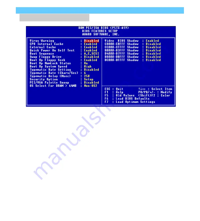
To enter this section of the Setup program, highlight this menu
item in the main menu and press the Enter key. The followingscreen will appear.
Страница 1: ...P5TX Apro Mainboard User s Manual...
Страница 2: ...tents of this publication are subject to change The manufacturer reserves the right to alter the contents of this publication at any time and without notice The contents of this publica tion may conta...
Страница 3: ...ards Slots 1 6 Memory Sockets Modules 1 7 CPU Socket CPU 1 7 Port Controller Connections 1 7 2 Using Your Mainboard 2 1 System Controls 2 1 Hardware Controls Indicators 2 1 CMOS Setup Utility Controls...
Страница 4: ...r Tables Illustrations 3 12 Adding An IDE Peripheral 3 16 IDE Transfer Modes 3 16 Installing IDE Devices 3 18 4 P5TX Apro Reference Information 4 1 Using This Section 4 1 Jumper Configuration Summary...
Страница 5: ...k that contains this manual It is installed on the Support CD and there is also an installation file that will automatically run the Acrobat Reader installer program to install it on your system hard...
Страница 6: ...are shortcuts to the topic dis played on the button This manual also uses some icons to call your attention to important information The icons appear in the sidebar and rep resent the following Impor...
Страница 7: ...inboard Cable Pack 1 Floppy Controller Cable 1 IDE Controller Cable Support Disk Driver Files Folder Manual Folder Adobe Acrobat Folder The mainboard comes with IDE Bus Master drivers for sev eral Ope...
Страница 8: ...Enhanced IDE and Floppy Disk Drive connectors have a notch in one side to orient the cables correctly The mainboard comes with one IDE cable If you install devices on the second IDE channel with anot...
Страница 9: ...t 7 PCI Slots 4 3 2 1 Battery ISA Slots 3 2 1 Intrusion USB Port DIMM3 DIMM2 DIMM1 IR Port Case Features Fan Power Wake Up Fan Power The COM1 and COM2 ports are underneath the Parallel port The USB po...
Страница 10: ...a legacy of the original IBM PC AT design They are 16 bit slots that run at a moderate bus speed There are many kinds of expansion cards that use this slot design to connect to the computer some of t...
Страница 11: ...e lever at the side of the socket latches the CPU in place when it is down and releases it when raised If you want to install a CPU upgrade or are installing a CPU on the board for the first time plea...
Страница 12: ...P5TX Apro User s Manual 1 Package Product Information 1 8...
Страница 13: ...out the parts of the CMOS Setup Utility that allow you customize some sys tem features Hardware Controls Indicators There are some control features and status indicators that con nect from the mainboa...
Страница 14: ...ended Pin 1 Pin 2 Pin 3 Reset Switch 9 10 Pressing the Reset switch restarts the system Keyboard Lock 11 12 Disables keyboard via a lock mounted on front panel of the case Speaker 13 16 Connects to th...
Страница 15: ...ery supported memory on the board The BIOS uses this record to function as an interface between the system hardware and the operating system Most of the settings in the CMOS Setup Utility are made aut...
Страница 16: ...some system features includ ing Virus Warning Boot Se quence and Security Option Virus Warning When enabled monitors the primary hard disk boot sec tor and warns of any attempt to write to it Boot Seq...
Страница 17: ...etup util ity allows you to configure the power management features supported by the BIOS These can also operate in tandem with Operating System power management features You can use the Min Saving or...
Страница 18: ...rt in the CMOS Setup Utility Parallel Port The parallel port can be configured as a Standard ECP or EPP parallel port in the CMOS Setup Utility PS 2 Keyboard Port PS 2 Mouse Port stacked USB ports two...
Страница 19: ...Peripherals This section of the setup util ity configures the IDE and Floppy controllers and the settings for the external ports This section enables and con figures the optional USB and Infrared fea...
Страница 20: ...e in the CMOS Setup utility s Power Management Setup section is set to Enabled the system will turn the fans off when the system is in Suspend mode Modem Wake Up The J19 connector on the mainboard is...
Страница 21: ...inboard supports hard disks that use UltraDMA data transfer You attach an UltraDMA drive to one of the IDE cables If you use the Optimum Settings feature in the CMOS Setup utility the system will auto...
Страница 22: ...ogram to adjust settings as noted in this and the next section To run the CMOS Setup Utility press the Del or Delete key while the computer is starting up before the operating starts to load The utili...
Страница 23: ...al 2 Using Your Mainboard 2 11 CMOS Setup Utility This is the main screen for the setup utility from which you access its various sections The function and use of each section is covered in Section 4...
Страница 24: ...replaces the existing one You do this using software that comes on the Support Disk There is an explana tion of how to install a BIOS update in a readme text file in cluded with the program Bus Maste...
Страница 25: ...Cards Slots ISA expansion cards often use system resources in the form of IRQs and DMA channels Newer cards that comply with the Plug and Play PnP standard are designed to allow the Operating Sys tem...
Страница 26: ...on Configuring Expansion Card Resources In CMOS Setup The CMOS Setup Utility which is covered in detail in Section 4 Reference Information has a section called PNP PCI Configu ration The default setti...
Страница 27: ...t screen for this section when Setup De faults are loaded If you need to manually configure the IRQ settings set the first item on the screen to the Manual setting See the next page If you install an...
Страница 28: ...can individually configure the IRQ DMA channel settings The individual defaults are for PnP cards and will still use all the items listed to automatically assign resources as needed If you are instal...
Страница 29: ...y ISA expansion card Legacy cards by definition are not PnP compliant and must be manually configured if they require an IRQ or DMA chan nel See the card manual for specifics When an item in the list...
Страница 30: ...ou can tell how much by checking the configuration screen that appears when the computer is starting up With some memory installed there may be one or two sockets available to add additional memory Me...
Страница 31: ...in detail The sockets are num bered DIMM1 to DIMM3 start ing from the top socket in the picture Modules press into place and are held in position by a retaining clamp at each end of the socket When y...
Страница 32: ...the module into the socket it may be oriented the wrong way Turn the module around and try again You shouldn t need to force it If All Sockets Are Occupied If you want to install more memory and there...
Страница 33: ...e Clock Multiplier Factor Set the CPU Voltage You configure the CPU settings by adjusting jumper settings on the board In order to do this you will need to know some information about the CPU you plan...
Страница 34: ...vendor s information should tell you what these factors should be P Rated CPUs Cyrix IBM and AMD all make Pentium class CPUs that are performance rated at an Intel Pentium equivalent speed but ac tua...
Страница 35: ...166MHz 66 6MHz 2 5 200MHz 66 6MHz 3 0 233MHz 66 6MHz 3 5 Cyrix IBM CPUs 6X86 P120 100MHz 50MHz 2 0 P133 110MHz 55MHz 2 0 P150 120MHz 60MHz 2 0 P166 133MHz 66 6MHz 2 0 P200 150MHz 75MHz 2 0 6X86MX 150M...
Страница 36: ...tings are listed in the tables as follows Where two pins are shorted connected by a jumper cap on a three or more pin jumper the shorted pins are listed e g 1 2 or For a two pin jumper On if the cap...
Страница 37: ...sections Pins 1 6 9 14 17 22 separated by pinless spacers Internal Clock Factor JP1 1 5x 3 5x 1 3 2 4 Default 2 0x 1 3 4 6 2 5x 3 5 4 6 3 0x 3 5 2 4 Jumper JP1 is divided into three sections Pins 1 6...
Страница 38: ...14 17 22 10 18 13 21 9 JP1 60MHz 14 17 22 10 18 13 21 9 JP1 61 6MHz 14 17 22 10 18 13 21 9 JP1 66MHz 14 17 22 10 18 13 21 9 JP1 68 4MHz 14 17 22 10 18 13 21 9 JP1 75MHz 14 17 22 10 18 13 21 JP1 1 5x 3...
Страница 39: ...P5TX Apro User s Manual 3 Reconfiguring Your Mainboard 3 15 Jumper Locations The illustration above shows the location of the jumpers il lustrated on the previous page Socket 7 JP1 JP2 JP4...
Страница 40: ...board chipset The transfer of data between the hard disk and the system takes place using one of a number of transfer modes either one of several PIO modes or UltaDMA mode Although there are several...
Страница 41: ...Defaults settings for this screen You can install IDE devices under these settings and the system will automati cally detect and set the best mode for each device You can also set the transfer mode f...
Страница 42: ...need to install devices on the second channel you will need to get another IDE cable These are a standard and inexpensive item that you can generally find at any computer supply store One edge of the...
Страница 43: ...er are for connecting to IDE devices The connector on the end is for the Master device and the connector in the middle is for the Slave device IDE Devices CMOS Setup When you install a new hard disk d...
Страница 44: ...P5TX Apro User s Manual 3 Reconfiguring Your Mainboard 3 20...
Страница 45: ...ctor Summary Supported CPUs System Memory Configuration Specifications CMOS Setup Utility Summary Using This Section The information in this section is presented in a summary for mat to make it easy t...
Страница 46: ...ket 7 PCI Slots 4 3 2 1 Battery ISA Slots 3 2 1 Intrusion USB Port DIMM3 DIMM2 DIMM1 IR Port Case Features Fan Power Wake Up Fan Power JP1 JP2 JP4 The COM1 and COM2 ports are underneath the Parallel p...
Страница 47: ...p is in place and Off if a cap is not in place In the jumper illustrations the Pin 1 position is shaded and the jumpers shown in a bird s eye view look like this A jumper with a cap in position looks...
Страница 48: ...tions Pins 1 6 9 14 17 22 separated by pinless spacers Internal Clock Factor JP1 1 5x 3 5x 1 3 2 4 Default 2 0x 1 3 4 6 2 5x 3 5 4 6 3 0x 3 5 2 4 Jumper JP1 is divided into three sections Pins 1 6 9 1...
Страница 49: ...7 22 10 18 13 21 9 JP1 60MHz 14 17 22 10 18 13 21 9 JP1 61 6MHz 14 17 22 10 18 13 21 9 JP1 66MHz 14 17 22 10 18 13 21 9 JP1 68 4MHz 14 17 22 10 18 13 21 9 JP1 75MHz 14 17 22 10 18 13 21 JP1 1 5x 3 5x...
Страница 50: ...or connects to 2 device cable End device is Secondary Master middle is Slave J10 Case Features Connects to case features Pin 1 3 Power On LED Pin 4 5 Suspend Switch Pin 6 8 Suspend LED Pin 9 10 Reset...
Страница 51: ...4 7 Pin 1 3 Power On LED Pin 4 5 Suspend Switch Pin 6 8 Suspend LED Pin 9 10 Reset Switch Pin 11 12 Keyboard Lock Pin 13 16 Speaker Pin 17 18 Hard Disk LED Pin 19 20 Power Switch J10 Case Features Con...
Страница 52: ...the use of all Pentium class processors from all three vendors including those with MMX features The correct jumper configuration automatically sets the required power configuration for the CPU Proces...
Страница 53: ...on the CPU The following information is a guide to reading the markings AMD K5 PR100 A B Q 100MHz Internal Clock Speed CPU Model P Rating 75 90 100 120 133 150 166 Package Type A SPGA 296 pin Operatin...
Страница 54: ...Internal Clock Speed Core Frequency 100 110 120 133 150 CPU Model 6x86 6x86L P Rating 90 120 133 150 166 200 Core Voltage Range Midpoint 3 3V 3 52V 2 5V 2 7V VCC Specification Full spec 3 15V 3 7V C s...
Страница 55: ...Memory Configurations You can install any combination of module sizes as long as you follow these requirements All modules must be 3 3 Volt All modules have same operating speed e g 60ns Other than th...
Страница 56: ...Utility This mainboard uses the Award system BIOS It is stored in a Flash ROM memory chip on the mainboard The BIOS uses a software program also stored on the same chip to create a sys tem configurati...
Страница 57: ...P5TX Apro User s Manual 4 Reference Information 4 13...
Страница 58: ...to move around the screen and select a menu item An item is highlighted when it is selected Change Color Change the program color scheme by pressing Shift F2 The section at the bottom of the screen d...
Страница 59: ...main sections Supervisor Password User Password Sets a system password which is configured by the Security Option item in BIOS Features Setup IDE HDD Auto Detection Automatically detects the drive pa...
Страница 60: ...the control commands for this level of the program You execute a command by pressing the key for that command The program commands are Quit This command will close the Setup program when you press the...
Страница 61: ...hem except for adjusting the Date and Time entries if necessary Date Time The first two lines on the screen are the date and time settings for the system clock Hard Disk Type Parameters Use the IDE HD...
Страница 62: ...tual physical address The maximum drive size sup ported is 8 4GB Large For 1GB or smaller drives with more than 1024 cylinders and no LBA support This access mode causes the Operating Sys tem to treat...
Страница 63: ...efault setting is Disabled Video Display Types You set this according to the type of display card in your sys tem This should normally be left on EGA VGA The options are EGA VGA Mono for Hercules or M...
Страница 64: ...ro User s Manual 4 Reference Information 4 20 BIOS Features Setup To enter this section of the Setup program highlight this menu item in the main menu and press the Enter key The following screen will...
Страница 65: ...d when it is selected Modify To change the setting of a highlighted selection you can press either the Page Up PU and Page Down PD keys or the Plus and Minus keys Pressing a key once will switch to th...
Страница 66: ...is Enabled External Cache This is the Level 2 external cache of either 256KB or 512KB Leave this enabled to maintain system performance The default setting is Enabled Quick Power On Self Test This fea...
Страница 67: ...t which mode the numeric key pad on an IBM compatible extended keyboard is set to when the computer boots up The options are On Numeric keypad mode Default Off Cursor control mode Security Option This...
Страница 68: ...ting The default setting Non OS2 is for all other operating systems Video BIOS Shadow This copies the video display card BIOS into system DRAM to increase display speed and is required for system perf...
Страница 69: ...enu Commands The menu commands for this screen are the same as for the BIOS Features Setup screen Auto Configuration Everything on this screen except for the Memory Hole item is set automatically when...
Страница 70: ...26 Memory Hole At 15M 16M Some special add on cards require a 1MB address space be tween 15 and 16MB The documentation for this type of card should tell you if it needs this The default setting is Dis...
Страница 71: ...Management Setup To enter this section of the Setup program highlight this menu item in the main menu and press the Enter key The following screen will appear Menu Commands The menu commands for this...
Страница 72: ...Management This controls the entire power management scheme There are four settings User Defined You set the power saving options manually Disable Turns off all power management Max Saving Maximizes...
Страница 73: ...n t have this type of monitor use the Blank option DPMS Display Power Management System allows the BIOS to control the video dis play card if the card has the DPMS feature V H SYNC Blank Default Blank...
Страница 74: ...is in User Define mode The de fault setting is Disabled When the system goes into power sav ing mode power management will skip to the next mode in the sequence if this is disabled Suspend Mode This...
Страница 75: ...y which the CPU speed is cut back when power saving initiates The settings are 62 5 Default 75 87 5 12 5 25 37 5 50 ZZ Active In Suspend This item puts the cache controller into sleep mode when the sy...
Страница 76: ...ant Off CPU Fan Off In Suspend In the default Enabled setting when a CPU Fan is connected to one of the fan power connectors on the mainboard the fan will turn off when the system is in Suspend mode T...
Страница 77: ...et to Enabled The defaults are shown above Power Supply Type This line indicates the type of power supply connected to the mainboard The default setting ATX enables the system to make use of ATX power...
Страница 78: ...CI Configuration To enter this section of the Setup program highlight this menu item in the main menu and press the Enter key The following screen will appear Menu Commands The menu commands for this...
Страница 79: ...set this line to Manual the screen changes as shown above and allows manual configuration In general you should only need to do this if you are installing an ISA card that requires manual configurati...
Страница 80: ...fault ISA PCI SLOT1 PCI SLOT2 PCI SLOT3 PCI SLOT4 If you set this option to ISA both the Primary IDE INT and Secondary IDE INT options below it will not appear on the screen Primary Secondary IDE INT...
Страница 81: ...The settings are not optimal and turn off all the performance features Standard CMOS Setup is not affected by this command Load Optimized Settings To use this command highlight it in the main menu and...
Страница 82: ...ormation 4 38 Integrated Peripherals This section sets the IDE transfer mode for all IDE channels It also configures the other onboard ports Menu Commands The menu commands for this screen are the sam...
Страница 83: ...of a device in any of these positions when they are set to Auto the recommended setting Alternatively you can set the mode manually Modes 0 to 4 are supported Primary Master Master Slave UltraDMA The...
Страница 84: ...default 2F8 IRQ3 Onboard serial port COM2 default 3E8 IRQ4 2E8 IRQ3 Disabled UART 2 Mode Sets mode for the second serial port UART If you select an IR module type the second serial port will not be a...
Страница 85: ...ons are SPP default ECP EPP EPP SPP ECP If you set this option to SPP or EPP SPP the ECP Mode Use DMA option will not appear on the screen If you set this option to SPP or ECP the Parallel Port EPP Ty...
Страница 86: ...s screen Warning Messages and PC Status The Warning Messages section has settings that con trol the monitoring function The PC Status section displays the current status of the listed items as detecte...
Страница 87: ...nabled Mainboard Temperature Enabled Chassis Enabled PC Status When you call up the PC Health Monitor screen this section displays the current readings from the onboard sensor The read ings are for th...
Страница 88: ...ssword the Security Option line in BIOS Features Setup controls when the password is required You can set the option to require the password when the system boots up or when calling up the CMOS Setup...