ECS P4VXMS Скачать руководство пользователя страница 18


12 

I

I

n

n

s

s

t

t

a

a

l

l

l

l

i

i

n

n

g

g


t

t

h

h

e

e


M

M

a

a

i

i

n

n

b

b

o

o

a

a

r

r

d

d


i

i

n

n


a

a


C

C

a

a

s

s

e

e


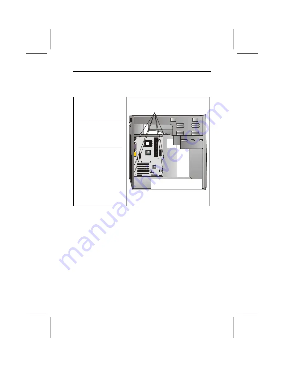
Refer to the following illustration and instructions for installing 
the mainboard in a case: 

This illustration shows 
an example of a main-
board being installed in 
a tower-type case: 

Note:

  Do not over-

tighten the 
screws as this 
can stress the 
mainboard. 

Most system cases have 
mounting brackets in-
stalled in the case, 
which correspond to the 
holes in the mainboard. 
Place the mainboard 
over the mounting 
brackets and secure the 
mainboard onto the 
mounting brackets with 
screws. 

2. Secure the mainboard with 

screws where appropriate.

1. Place the mainboard 

over the mounting brackets.


Ensure that your case has an I/O template that supports the 
I/O ports and expansion slots on your mainboard. 


Содержание P4VXMS

Страница 1: ...o the contents hereof and specifically disclaims any implied warranties of merchantability or fitness for any particular purpose The manufacturer reserves the right to revise this publication and to make changes from time to time in the content hereof without obliga tion of the manufacturer to notify any person of such revision or changes Trademark Recognition Microsoft MS DOS and Windows are regi...

Страница 2: ...e harmful interference to radio or television reception which can be determined by turning the equipment off and on the user is encouraged to try to correct the interference by one or more of the following measures Reorient or relocate the receiving antenna Increase the separation between the equipment and the receiver Connect the equipment onto an outlet on a circuit different from that to which ...

Страница 3: ...nd This device must accept any interference received includ ing interference that may cause undesired operation Canadian Department of Communications This class B digital apparatus meets all requirements of the Cana dian Interference causing Equipment Regulations Cet appareil numérique de la classe B respecte toutes les exigences du Réglement sur le matériel brouilieur du Canada ...

Страница 4: ...page 1 Chapter 2 Installing the Mainboard Describes installation of main board components Go to page 7 Chapter 3 Using BIOS Provides information on using the BIOS Setup Utility Go to page 35 Chapter 4 Using the Mainboard Software Describes the mainboard soft ware Go to page 70 Appendix A Setting Jumpers Provides a reference to the jumpers on the mainboard Go to page 77 ...

Страница 5: ...gs 10 Installing the Mainboard in a Case 12 Connecting Case Components 13 The Panel Connector 14 Installing Hardware 15 Installing the Processor 15 Installing Memory Modules 20 Installing a Hard Disk Drive CD ROM 22 Installing a Floppy Diskette Drive 25 Installing Add on Cards 26 Connecting Optional Devices 28 Connecting I O Devices 33 External Connector Color Coding 34 CHAPTER 3 35 Using BIOS 35 ...

Страница 6: ...Safe Defaults Option 67 Load Optimized Defaults Option 67 Set Supervisor and User Passwords Options 68 Save Exit Setup Option 69 Exit Without Saving 69 CHAPTER 4 70 Using the Mainboard Software 70 About the Software CD ROM 70 Auto installing under Windows 98 71 Running Setup 72 Drivers Installation 73 Utility Software Reference 75 APPENDIX A 76 Setting Jumpers 77 Jumper Settings 77 The Panel Conne...

Страница 7: ... 423 that accommodates In tel Pentium 4 processors supporting system bus speeds of 400 MHz The P4VXMS incorporates the VIA VT8753 V845PRO Northbridge and VT8233 Southbridge chipsets which supports the AC 97 audio codec C Ch he ec ck kl li is st t Compare the mainboard s package contents with the following checklist Standard Items One mainboard One diskette drive ribbon cable and bracket One IDE dr...

Страница 8: ...ace providing vivid 3D graphics and video performance An ATA 100 interface on the chipset which helps boost system performance by providing a high speed connection to ATA 100 Hard Disk Drives delivering maximum sustained data transfer rates of 100 MB sec Additional key features include support for six USB ports an AC 97 link for audio and modem hardware monitoring and ACPI OnNow power management M...

Страница 9: ... P4VXMS PCI slots are capable of Ultra DMA bus mastering with transfer rates of 33 66 100 MB sec Integrated I O The mainboard has a full set of I O ports and con nectors Two PS 2 ports for mouse and keyboard Two serial port One parallel port One MIDI game port Six USB ports two backpanel ports onboard USB headers providing four extra ports Audio jacks for microphone line in and line out One onboar...

Страница 10: ...4 M Ma ai in nb bo oa ar rd d C Co om mp po on ne en nt ts s ...

Страница 11: ... CMOS jumper JP2 Wake on Keyboard USB activity JP3 BIOS flash protection jumper JP4 External SMI JP5 Single color LED LED1 LED 3 VSB for SDRAM red PANEL Front panel header PCI1 PCI3 Three 32 bit add on card slots SIR Serial infrared cable header LSIR Serial infrared cable header SMARTIO Connector used with media storage devices LUSB1 Connector for front panel USB ports USB2 Connector for front pan...

Страница 12: ... all the features required The mainboard can support one floppy diskette drive and four enhanced IDE drives En sure that your case has sufficient power and space for all the drives that you intend to install Most cases have a choice of I O templates in the rear panel Make sure that the I O template in the case matches the I O ports installed on the rear edge of the mainboard This mainboard has a M...

Страница 13: ...lling the mainboard Wear a grounding strap attached to a grounded device to avoid damage from static electricity Discharge static electricity by touching the metal case of a safely grounded object before working on the mainboard Leave components in the static proof bags they came in Hold all circuit boards by the edges Do not bend cir cuit boards ...

Страница 14: ...Setting Jumpers Go to page 9 Installing the Mainboard in a Case Go to page 7 Installing Case Components Go to page 13 Installing the CPU Go to page 15 Installing Memory Go to page 20 Installing an HDD and CD ROM Drive Go to page 22 Installing an FDD Go to page 25 Installing Add on Cards Go to page 26 Connecting Options Go to page 28 Connecting Peripheral I O Devices Go to page 33 Note The appendix...

Страница 15: ...figuration op tions Jumpers with more than one p in are numbered When setting the jumpers ensure that the jumper caps are placed on the correct pins Short Open This illustration shows a 2 pin jumper When the jumper cap is placed on both pins the jumper is SHORT If you remove the jumper cap or place the jumper cap on just one pin the jumper is OPEN 1 2 3 This illustration shows a 3 pin jumper Pins ...

Страница 16: ...10 Checking Jumper Settings The following illustration shows the location of the mainboard jumpers Pin 1 is labeled ...

Страница 17: ...set BIOS 1 Turn the system off 2 Short pins 2 and 3 on JP1 3 Return the jumper to the normal setting 4 Turn the system on The BIOS is returned to the default set tings JP2 Wake on Keyboard USB activity This jumper enables any USB keyboard activity to power up a system that had previously been in a standby or sleep state JP3 BIOS Flash Protect Jumper This jumper is used to protect the BIOS from bei...

Страница 18: ... over tighten the screws as this can stress the mainboard Most system cases have mounting brackets in stalled in the case which correspond to the holes in the mainboard Place the mainboard over the mounting brackets and secure the mainboard onto the mounting brackets with screws 2 Secure the mainboard with screws where appropriate 1 Place the mainboard over the mounting brackets Ensure that your c...

Страница 19: ...he mainboard into a case you can begin connecting the mainboard components Refer to the fol lowing 1 Connect the case power supply connector to ATX1 2 Connect the CPU cooling fan cable to CPUFAN1 3 Connect the case cooling fan connector to CASFAN1 The following page explains how to make PANEL connections ...

Страница 20: ... to the table below for information Device Pins Empty 10 N C 9 Power ON OFF 6 8 Reset Switch 5 7 Green LED Indicator 2 4 HDD LED 1 3 HDD LED Pins 1 3 2 1 Reset Switch Pins 5 7 Power Switch Pins 6 8 Green LED Pins 2 4 Empty Pin 10 10 9 N C Pin 9 Note The plus sign indicates a pin which must be con nected to a positive voltage ...

Страница 21: ...stalling the Processor This mainboard automatically determines the CPU clock fre quency and system bus frequency for the processor You may be able to change these settings by making changes to jump ers on the mainboard or changing the settings in the system Setup Utility We strongly recommend that you do not over clock processors or other components to run faster than their rated speed Warning Ove...

Страница 22: ...16 CPU Installation Procedure The following illustration shows CPU installation components Note The pin 1 corner on the CPU and socket is empty ...

Страница 23: ...and raise the locking lever to the upright position 2 Match the pin 1 corner on the CPU socket and the pin 1 corner on the processor and insert the processor into the socket Do not use force 3 Swing the locking lever down and hook it under the latch on the edge of the socket 4 Apply thermal grease to the top of the CPU ...

Страница 24: ...18 5 Lower the CPU fan heatsink unit onto the CPU and CPU socket and then use the retention module clamps to snap the fan heatsink into place refer to diagram below ...

Страница 25: ...19 6 Plug the CPU fan power cable into the CPU cooling fan power supply CPUFAN1 on the mainboard ...

Страница 26: ...Access Memory The CPU supports 100MHz system bus The SDRAM DIMMS can synchronously work with 100 MHz or operates over a 133 MHz system bus Note SDRAM provides 800 MBps or 1 GBps data trans fer depending on whether the bus is 100MHz or 133MHz The DRAM size can support 64MB 128MB 256MB 512MB The maximum memory can support up to 3GB registered and 1 5GB unbuffered Installation Procedure ...

Страница 27: ...DIMM slot down 2 Align the memory module with the slot The DIMM slots are keyed with notches and the DIMMs are keyed with cutouts so that they can only be installed correctly 3 Check that the cutouts on the DIMM module edge connector match the notches in the DIMM slot Cutout Notch Latch Latch 4 Install the DIMM module into the slot and press it firmly down until it seats correctly The slot latches...

Страница 28: ... devices to the secon dary IDE channel IDE devices have jumpers or switches that are used to set the IDE device as MASTER or SLAVE Refer to the IDE device user s manual When installing two IDE devices on one cable ensure that one device is set to MASTER and the other de vice is set to SLAVE The documentation of your IDE device explains how to do this About UltraDMA This mainboard supports Ultra DM...

Страница 29: ...or Each connector has the pin 1 side clearly marked The pin 1 side of each ribbon cable is always marked with a colored stripe on the cable 3 Plug an IDE cable connector into the hard disk drive IDE connector It doesn t matter which connector on the cable you use Ensure that the pin 1 side of the cable is matched with the pin 1 side of the connector Refer to the previous note B 4 Plug a power cabl...

Страница 30: ...ug the IDE cable into IDE1 A If you have already installed an HDD use the other connector on the IDE cable Note Ribbon cable connectors are usually keyed so that they can only be installed correctly on the device connector If the connector is not keyed make sure that you match the pin 1 side of the cable connector with the pin 1 side of the device connector Each connector has the pin 1 side clearl...

Страница 31: ...auto matically detect your CD ROM DVD drive If it doesn t enter the Setup Utility and configure the CD ROM DVD drive that you have installed See IDE Primary Secondary Master Slave Auto on page 40 for more information Installing a Floppy Diskette Drive The mainboard has a floppy diskette drive FDD interface and ships with a diskette drive ribbon cable that supports one or two floppy diskette drives...

Страница 32: ... up your system go immediately to the Setup Utility to configure the floppy diskette drives that you have installed See Standard CMOS Features on page 39 for more information Installing Add on Cards This mainboard has three 32 bit PCI Peripheral Components Interconnect expansion slots one 4xAGP slot and one CNR slot 4xAGP Slot The 4xAGP slot is used to install a graphics adapter that supports the ...

Страница 33: ... add on card into the expansion slot Ensure that the edge connector is cor rectly seated in the slot 3 Secure the metal bracket of the card to the system case with a screw Note For some add on cards for example graphics adapt ers and network adapters you have to install drivers and software before you can begin using the add on card ...

Страница 34: ... board s optional devices LAUDIO Mic Speaker Out header Pin Signal Name Pin Signal Name 1 3 5 7 9 11 13 15 Active LINE Out R GND aLO GND 12 12V 1A MIC Front LINE Out R Front LINE Out L GND tLO 2 4 6 8 10 12 14 16 Active LINE Out L GND aLO GND 12 Cut away GND MIC LINE Next R LINE Next L No pin ...

Страница 35: ...ium CPUs used for power management This interrupt is also used for virus checking Pin Signal Name 1 2 EXTSMI GND USB2 USB3 Front panel USB headers The mainboard has USB ports installed on the rear edge I O port array Some computer cases have a special module that mounts USB ports at the front of the case If you have this kind of case use auxiliary USB connectors USB2 and USB3 to connect the front ...

Страница 36: ...ke On LAN WOL feature When your system is in a power saving mode any LAN signal automatically r e sumes the system You must enable this item using the Power Management page of the Setup Utility Pin Signal Name 1 2 3 5VSB Ground SENSE If you have installed a modem use the cable provided with the modem to plug into the mainboard WOM1 connector This enables the Wake On Modem WOM feature When your sys...

Страница 37: ...E 11 12 13 14 15 16 17 18 19 20 VCC3 VCC3 GND GND 5VSB GND GND RESERVED GND VCC5 VCC5 LSIR Serial infrared port 2 The mainboard supports a Serial Infrared SIR data port In frared ports allow the wireless exchange of information between your computer and similarly equipped devices such as printers laptops Personal Digital Assistants PDAs and other computers Pin Signal Name 1 2 3 4 5 VCC No pin IRRX...

Страница 38: ...ge of information between your computer and similarly equipped devices such as printers laptops Personal Digital Assistants PDAs and other computers Pin Signal Name Pin Signal Name 1 3 5 NC VCC IRTX 2 4 6 Key pin Ground IRRX Note For SIR and LSIR select one from the two types of Serial infrared port supported by this mainboard ...

Страница 39: ...rts Use the USB ports to connect USB devices LPT1 Use LPT1 to connect printers or other parallel communications devices COM1 2 Use the COM ports to connect serial devices such as mice or fax modems COM1 is identified by the system as COM1 3 COM2 is identified by the system as COM2 4 Game Port Use the game port to connect a joy stick or a MIDI device Audio Ports Use the three audio ports to connect...

Страница 40: ...ne out Lime Digital monitor flat panel White IEEE 1394 Grey Microphone Pink MIDI Game Gold Parallel Burgundy PS 2 compatible keyboard Purple PS 2 compatible mouse Green Serial Teal or Turquoise Speaker out subwoofer Orange Right to left speaker Brown USB Black Video out Yellow SCSI network telephone modem None This concludes Chapter 2 The next chapter covers the BIOS ...

Страница 41: ...eters The parameters are stored in battery backed up CMOS RAM that saves this information when the power is turned off When the system is turned back on the system is configured with the values you stored in CMOS The BIOS Setup Utility enables you to configure Hard drives diskette drives and peripherals Video display type and display options Password protection from unauthorized use Power manageme...

Страница 42: ...ake any changes in the future This Setup Utility should be used when changing the system configuration when a configuration error is detected and you are prompted to make changes to the Setup Utility when trying to resolve IRQ conflicts when making changes to the Power Management con figuration when changing the password or making other changes to the Security Setup ...

Страница 43: ...tup PnP PCI Configurations PC Health Status Frequency Voltage Control Load Fail Safe Defaults Load Optimized Defaults Set Supervisor Password Set User Password Save Exit Setup Exit Without Saving Esc Quit Select Item F10 Save Exit Setup Time Date Hard Disk Type BIOS Navigation Keys The BIOS navigation keys are listed below Key Function Esc Exits the current menu Scrolls through the items on a menu...

Страница 44: ...tem diskette you created in Step 3 5 Turn off your computer and insert the system diskette in your computer s diskette drive You might need to run the Setup Utility and change the boot priority items on the Advanced BIOS Features Setup page to force your computer to boot from the floppy diskette drive first 6 At the A prompt type the Flash Utility program name and press Enter You see a screen simi...

Страница 45: ...lues for the option Use the cursor arrow keys to scroll through the items in the submenu In this manual default values are enclosed in parenthesis Submenu items are denoted by a triangle Standard CMOS Features This option displays basic information about your system CMOS Setup Utility Copyright C 1984 2001 Award Software Standard CMOS Features Item Help Date mm dd yy Tue July 11 2000 Time hh mm ss...

Страница 46: ...omp 0 Landing Zone 0 Sector 0 Menu Level To auto detect the HDD s size head on this channel Move Enter Select PU PD Value F10 Save ESC Exit F1 General Help F5 Previous Values F6 Fail Safe Defaults F7 Optimized Defaults IDE HDD Auto Detection Press Enter while this item is highlighted to prompt the Setup Utility to automatically detect and configure an IDE de vice on the IDE channel Note If you are...

Страница 47: ...CMOS Features page Drive A Drive B 1 44M 3 5 in None These items define the characteristics of any diskette drive at tached to the system You can connect one or two diskette drives Floppy 3 Mode Support Disabled Floppy 3 mode refers to a 3 5 inch diskette with a capacity of 1 2 MB Floppy 3 mode is sometimes used in Japan Video EGA VGA This item defines the video mode of the system This main board ...

Страница 48: ...ion is enabled and someone attempts to write data into this area BIOS will show a warning message on screen and alarm beep Move Enter Select PU PD Value F10 Save ESC Exit F1 General Help F5 Previous Values F6 Fail Safe Defaults F7 Optimized Defaults Anti Virus Protection Disabled When enabled this item provides protection against viruses that try to write to the boot sector and partition table of ...

Страница 49: ...ces specified under the First Second and Third boot de vices Swap Floppy Drive Disabled If you have two floppy diskette drives in your system this item allows you to swap the assigned drive letters so that drive A becomes drive B and drive B becomes drive A Boot Up Floppy Seek Enabled If this item is enabled it checks the size of the floppy disk drives at start up time You don t need to enable thi...

Страница 50: ... Self Monitoring Analysis and Reporting Technology system is a diagnostics technology that monitors and predicts device performance S M A R T software resides on both the disk drive and the host computer The disk drive software monitors the internal performance of the motors media heads and electronics o f the drive The host software monitors the overall reliability status of the drive If a device...

Страница 51: ...ou may introduce fatal er rors or recurring instability into your system CMOS Setup Utility Copyright C 1984 2001 Award Software Advanced Chipset Features Item Help DRAM Clock Drive Control Press Enter AGP P2P Bridge Control Press Enter CPU PCI Bus Control Press Enter Memory Hole Disabled System BIOS Cacheable Disabled Video RAM Cacheable Disabled Memory Parity ECC Check Disabled Menu Level Move E...

Страница 52: ...displays the frontside bus FSB frequency This is a display only item You cannot make changes to this field Current DRAM Frequency This item displays the memory DRAM frequency This is a display only item You cannot make changes to this field DRAM Clock SPD This item enables you to manually set the DRAM Clock We recommend that you leave this item at the default value DRAM Timing Manual Set this to t...

Страница 53: ...ly DRAM is refreshed entirely as the result of a single request This option allows you to determine the number of CPU clocks allocated for the Row Address Strobe RAS to accumulate its charge before the DRAM is refreshed If insuf ficient time is allowed refresh may be incomplete and data lost Active to Precharge 6T This item specifies the number of clock cycles needed after a bank active command be...

Страница 54: ...ics memory We recommend that you leave this item at the default value AGP Mode 4X This item allows you to enable or disable the caching of dis play data for the processor video memory Enabling AGP 4X Mode can greatly improve the display speed Disable this item if your graphics display card does not support this feature AGP Driving Control AUTO This item is used to signal driving current on AGP car...

Страница 55: ... PCI Bridge Control Item Help CPU to PCI Write Buffer Enabled PCI Master 0 WS Write Enabled PCI Delay Transaction Disabled Menu Level Move Enter Select PU PD Value F10 Save ESC Exit F1 General Help F5 Previous Values F6 Fail Safe Defaults F7 Optimized Defaults CPU to PCI Write Buffer Enabled When enabled writes from the CPU to PCU bus are buffered to compensate for the speed differences between th...

Страница 56: ...acheable Disabled These items allow the video and system to be cached in memory for faster execution Leave these items at the default value for better performance Memory Parity ECC Check Disabled Enable this item to allow BIOS to perform a parity check to the POST memory tests Select Enabled only if the system DRAM supports parity checking Press Esc to return to the previous screen ...

Страница 57: ...r Select PU PD Value F10 Save ESC Exit F1 General Help F5 Previous Values F6 Fail Safe Defaults F7 Optimized Defaults VIA OnChip IDE Device Scroll to this item and press Enter to view the following screen CMOS Setup Utility Copyright C 1984 2001 Award Software VIA OnChip IDE Device Item Help OnChip IDE Channel0 Enabled OnChip IDE Channel1 Enabled IDE Prefetch Mode Enabled Primary Master PIO Auto P...

Страница 58: ... slave de vice These four items let you assign which kind of PIO Programmed Input Output is used by IDE devices Choose Auto to let the system auto detect which PIO mode is best or select a PIO mode from 0 4 IDE Primary Secondary Master Slave UDMA Auto Each IDE channel supports a master device and a slave de vice This mainboard supports UltraDMA technology which provides faster access to IDE device...

Страница 59: ... Value F10 Save ESC Exit F1 General Help F5 Previous Values F6 Fail Safe Defaults F7 Optimized Defaults VIA 3058 AC97 Audio Auto Enables and disables the onboard audio chip Disable this item if you are going to install a PCI audio add on card VIA 3068 MC97 Modem Auto Enables and disables the onboard modem Disable this item if you are going to install an external modem Onboard LAN Device Enabled En...

Страница 60: ...isk drive controller Onboard Serial Port 1 3F8 IRQ4 This option is used to assign the I O address and address and interrupt request IRQ for onboard serial port 1 COM1 Onboard Serial Port 2 2F8 IRQ3 This option is used to assign the I O address and address and interrupt request IRQ for onboard serial port 2 COM2 UART Mode Select Normal This field is available if the Onboard Serial Port 2 field is s...

Страница 61: ...ended Capabilities Port ECP and Enhanced Parallel Port EPP are bi directional modes a l lowing both data input and output ECP and EPP modes are only supported with EPP and ECP aware peripherals ECP Mode Use DMA 3 When the onboard parallel port is set to ECP mode the paral lel port can use DMA 3 or DMA 1 Game Port Address 201 This item sets the I O address for the game port Midi Port Address 330 Th...

Страница 62: ... that does not support Plug and Play USB Mouse Support Disabled Enable this item if you plan to use a USB mouse IDE HDD Block Mode Enabled Enable this field if your IDE hard drive supports block mode Block mode enables BIOS to automatically detect the optimal number of block read and writes per sector that the drive can support and improves the speed of access to IDE devices ...

Страница 63: ...If the system is suspended or has been powered down by software it can be resumed by a wake up call that is gener ated by incoming traffic to a modem a LAN card a PCI card or a fixed alarm on the system realtime clock CMOS Setup Utility Copyright C 1984 2001 Award Software Power Management Setup Item Help ACPI function Enabled ACPI Suspend Type S1 POS Power Management Option User Define HDD Power ...

Страница 64: ...is set to Max Sav ing power saving modes occur after a short timeout If this item is set to Min Saving power saving modes occur after a longer timeout If the item is set to User Define you can insert your own timeouts for the power saving modes HDD Power Down Disable The IDE hard drive will spin down if it is not accessed within a specified length of time Options are from 1 Min to 15 Min and Disab...

Страница 65: ...4 Sec then you have to hold the power button down for four seconds to cause a software power down PWRON After PWR Fail Off This item enables your computer to automatically restart or re turn to its last operating status after power returns from a power failure IRQ Event Activity Detect Scroll to this item and press Enter to view the following screen CMOS Setup Utility Copyright C 1984 2000 Award S...

Страница 66: ... timeout counters w hen any activity is detected on the hard disk drive or the floppy diskette drive PCI Master OFF When set to Off any PCI device set as the Master will not power on the system PowerOn by PCI Card Disabled Use this item to enable PCI activity to wakeup the system from a power saving mode WOL WOM Ring Resume Disabled Use this item to enable LAN or modem activity to wakeup the syste...

Страница 67: ...2 Redir Disabled IRQ 10 Reserved Disabled IRQ 11 Reserved Disabled IRQ 12 PS 2 Mouse Enabled IRQ 13 Coprocessor Enabled IRQ 14 Hard Disk Enabled IRQ 15 Reserved Disabled Menu Level Move Enter Select PU PD Value F10 Save ESC Exit F1 General Help F5 Previous Values F6 Fail Safe Defaults F7 Optimized Defaults This screen enables you to set IRQs that will resume the sys tem from a power saving mode Se...

Страница 68: ...r USB Enabled Menu Level Select Yes if you are using a Plug and Play capable operating system Select No if you need the BIOS to configure non boot devices Move Enter Select PU PD Value F10 Save ESC Exit F1 General Help F5 Previous Values F6 Fail Safe Defaults F7 Optimized Defaults PNP OS Installed No Setting this option to Yes allows the PnP OS instead of BIOS to assign the system resources such a...

Страница 69: ...e IRQ 10 assigned to PCI Device IRQ 11 assigned to PCI Device IRQ 12 assigned to PCI Device IRQ 14 assigned to PCI Device IRQ 15 assigned to PCI Device Menu Level Legacy ISA for devices compliant with the original PC AT bus specification PCI ISA PnP for devices compliant with the Plug and Play standard whether designed for PCI or ISA bus architecture Move Enter Select PU PD Value F10 Save ESC Exit...

Страница 70: ...0V 3 30V 5 00V 12 00V Voltage Battery Current System Temp Current CPU Temp CPU FAN Speed CASE FAN Speed Menu Level MoveEnter Select PU PD Value F10 Save ESC Exit F1 General Help F5 Previous Values F6 Fail Safe Defaults F7 Optimized Defaults Shutdown Temperature Enables you to set the maximum temperature the system can reach before powering down System Component Characteristics These fields provide...

Страница 71: ...lock Default CPU Ratio X 8 Menu Level Move Enter Select PU PD Value F10 Save ESC Exit F1 General Help F5 Previous Values F6 Fail Safe Defaults F7 Optimized Defaults Auto Detect DIMM PCI Clk Enabled When this item is enabled BIOS will disable the clock signal of free DIMM and PCI slots Spread Spectrum Enabled If you enable spread spectrum it can significantly reduce the EMI Electro Magnetic Interfe...

Страница 72: ... so that Multiplier x Frontside Bus Frequency CPU Clock Speed For example if you have a processor that is rated to run at 450 MHz and the system is running a frontside bus frequency of 100 MHz you should select a multiplier of 4 5 so that 4 5 Multiplier x 100 MHz frontside bus 450 MHz CPU clock Press Esc to return to the previous screen ...

Страница 73: ...safe defaults for a specific option select and display that op tion and then press F6 Load Optimized Defaults Option This option opens a dialog box that lets you install optimized defaults for all appropriate items in the Setup Utility Press Y and then Enter to install the defaults Press N and then Enter to not install the defaults The optimized defaults place demands on the system that may be gre...

Страница 74: ...more than eight characters or numbers The Set Supervisor User Password item dif ferentiates between upper and lower case characters Press Enter after you have typed in the password If you are deleting a password that is already installed press Enter when the password dialog box appears You see a message that indicates that the password has been disabled PASSWORD DISABLED Press any key to continue ...

Страница 75: ...s item and press Enter to discard any changes that you have made in the Setup Utility and exit the Setup Util ity When the Exit Without Saving dialog box appears press Y to discard changes and exit or press N to return to the main menu Note If you have made settings that you do not want to save use the Exit Without Saving item and press Y to discard any changes you have made This concludes Chapter...

Страница 76: ...nd a brief description of each software program and the lo cation for your mainboard version More information on some programs is available in a README file located in the same directory as the software Note Never try to install software from a folder that is not specified for use with your mainboard Before installing any software always inspect the folder for files named README TXT INSTALL TXT or...

Страница 77: ...plorer Refer to Utility Folder Installation Notes later in this chapter The support software CD ROM disc loads automatically under Windows 98 ME When you insert the CD ROM disc in the CD ROM drive the autorun feature will automatically bring up the install screen The screen has three buttons on it Setup Browse CD and Exit Note If the opening screen doesn t appear double click the file setup exe in...

Страница 78: ...are correctly Some software is installed in separate folders for different op erating systems such as DOS WIN NT or WIN98 95 Always go to the correct folder for the kind of OS you are using To install the software execute a file named SETUP EXE or INSTALL EXE by double clicking the file and then following the instructions on the screen Exit The Exit button closes the Auto Setup window Running Setu...

Страница 79: ...ng screen appears 9 Check the box next to the items you want to install The default options are recommended 10 Click Next run the Installation Wizard An item installa tion screen appears 11 Follow the instructions on the screen to install the items Drivers and software are automatically installed in sequence Follow the onscreen instructions confirm commands and a l low the computer to restart a fe...

Страница 80: ...i io on n Insert the CD in the CD ROM drive and look for the Path doc file This file contains all the necessary information needed to begin the manual installation Look for the chipset and mainboard model then follow the di rectory and path to begin installing the drivers ...

Страница 81: ...S or write a new BIOS that is incorrect your system will malfunction Refer to Chapter 3 Using BIOS for more information PC CILLIN The PC CILLIN software program provides anti virus protec tion for your system This program is available for Windows 2000 ME 98SE and Windows NT Be sure to check the r e adme txt and install the appropriate anti virus software for your operating system We strongly recom...

Страница 82: ...om virus intrusion accidental deletions and from system cor ruption To install the Recovery Genius software program run SETUP EXE from the following directory UTILITY RECOVERY GENIUS ENG RECOVERYGENIUS Language Genius The Language Genius is a software based product that helps you to learn new languages To install the Language Genius software program run SETUP EXE from the following directory UTILI...

Страница 83: ...BIOS 12 Turn the system off 13 Short pins 2 and 3 on JP1 14 Return the jumper to the normal setting 15 Turn the system on The BIOS is returned to the default set tings JP2 Wake on Keyboard USB activity This jumper enables any USB keyboard activity to power up a system that had previously been in a standby or sleep state JP3 BIOS Flash Protect Jumper This jumper is used to protect the BIOS from bei...

Страница 84: ...ble below for information Device Pins Empty 10 N C 9 Power ON OFF 6 8 Reset Switch 5 7 Green LED Indicator 2 4 HDD LED 1 3 HDD LED Pins 1 3 2 1 Reset Switch Pins 5 7 Power Switch Pins 6 8 Green LED Pins 2 4 Empty Pin 10 10 9 N C Pin 9 Note The plus sign indicates a pin which must be con nected to a positive voltage ...

Отзывы: