


5.
连接电源线与电源接头:
c.
连接
24
针电源线与电源接头
4
针电源接头提供
CPU
电源。其电源接头与电
源线必须完全扣合。
b.
将
SATA
电源接头连接至
SATA
设备
a.
将
SATA
电缆连接至
SATA
硬盘
d.
连接
4
针电源线与电源接头
请注意电源接头与电源线必须完全扣合。
简体中文
26
当上述安装步骤完成后,请开始安装键盘,鼠标,
源并启
显示器等外围设备,然后连接电
动系统。请安装好所需的软件。
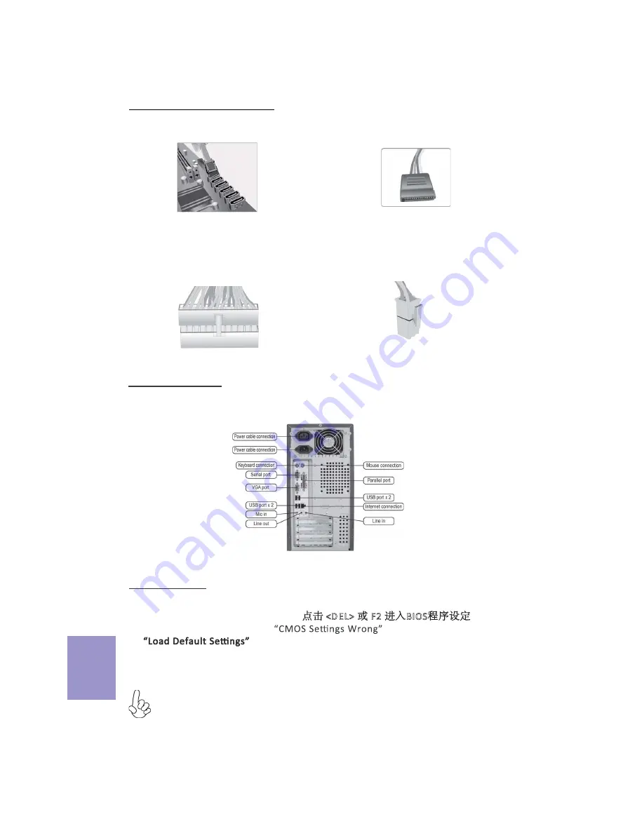
6.
连接机箱端口:
此说明内容中提供图片或安装方式仅供参考。
BIOS
使用设定
BIOS
程序画面会显示系统配置,同时提供操作选项让您设定系统参数。当开机时,
BIOS
会进行开机自我测试
(POST)
,请点击
<D EL>
或
F2
进入
BIOS
程序设定。第一次
开机时,
POST
画面可能会显示
信息,请进入
BIOS
选单 并选
择
将
BIOS
重新设定为默认值
(
更换
CPU
或内存等硬件变更也
可能会出现此信息
)
。
Содержание B85H3-M9
Страница 13: ...38 38 1 1 2 1 DIMM CPU CPU 1 2 CPU CPU 2 2 DIMM 0 0 3 1 I O I O 3 2 I O CPU CPU 11...
Страница 14: ...24 CPU ATX_12V 4 4 ATX_12V SATA SATA SATA SATA 4 24 ATX 12 BIOS BIOS POST POST DK t CMOS CPU 26 BIOS DEL F2...
Страница 19: ...1 1 1 3 3 1 1 2 3 2 DD DD DD 17...
Страница 25: ...23 1 1 1 2 1 2 1 2 DIMM 2 2 3 1 3 2 3 4...
Страница 26: ...24 SATA SATA 5 0 24 24 ATX 4 4 12 ATX 12 ATX 4 SATA SATA 6 BIOS F2 DEL POST CMOS BIOS...
Страница 27: ...1 CPU CPU 1 1 C P U 2 2 1 3 3 1 I O I O C P U C P U C P U C P U 1 2 CPU CPU 2 2 3 2 I O I O 4 25...
Страница 28: ...5 c 24 4 CPU b SATA SATA a SATA SATA d 4 26 6 BIOS BIOS BIOS POST DEL F2 BIOS POST BIOS BIOS CPU...
Страница 29: ...1 CPU CPU 1 1 2 2 1 DIMM 3 3 1 I O I O CPU CPU CPU CPU 1 2 CPU CPU 2 2 DIMM DIMM 3 2 I O 27 4...