ECS B85H3-M9 Скачать руководство пользователя страница 21

Paso 1. Instalación de la CPU y sistema de refrigeración de la CPU:

Guía de instalación del hardware

Pasos para realizar la instalación


Paso 2. Instalación de los módulos de memoria:

 of Motherboard:


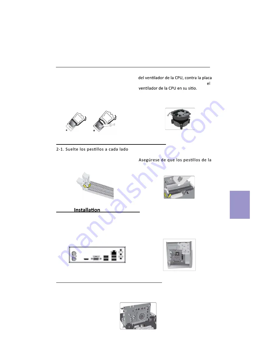
3-2.  Coloque la placa base dentro de la 
carcasa colocándola en la placa I/O. 
Asegure la placa base a la carcasa con 
tornillos.

1-1. Tire de la palanca hacia arriba, 
apartándola del zócalo. Alinee el 
borde  recortado de la CPU  con el

 borde dentado  del zócalo de la CPU. 

Coloque suavemente la CPU en la

 posición  correcta. Aplique una capa

 uniforme de  grasa térmica sobre
 la super

Į

cie de la CPU.

1-2. Gire y presione hacia abajo la sujeción 

base

 a través de los ori

Į

cios, para instalar 

de las ranuras DIMM.

2-2. Presione con 

Į

rmeza el DIMM hacia 

abajo hasta que asiente correctamente. 

ranura esten levantados y traben los 
extremos del DIMM.

3-1. Cambie la placa I/O trasera de la 
carcasa por la protección I/O 
proporcionada en el paquete de la 
placa base.


Español

19

Paso 4. Instalación de la tarjeta de expansión:

Quite el metal colocado en la ranura e inserte la tarjeta de expansión en la ranura. 
Presione con 

Į

rmeza la tarjeta hasta que quede perfectamente introducida en la r

Desp

anura.

ués vuelva a poner el tornillo en su posición.

Paso 3

Содержание B85H3-M9

Страница 1: ...ient or relocate the receiving antenna Increase the separation between the equipment and the receiver Connect the equipment onto an outlet on a circuit different from that to which the receiver is con...

Страница 2: ...Specifications 1 MotherboardComponents 3 HeaderPinDefinitionandJumperSettings 4 I OPorts 6 Multi language Quick Installation Guide 7 English 7 BrazilianPortuguese 9 Hindi 11 French 13 Deutsch 15 Russ...

Страница 3: ...000 Fast Ethernet Controller Wake on LAN and remote wake up support LGA1150 socket for Intel Haswell Processor Supports TDP up to 65W Note Please go to ECS website for the latest CPU support list 1 x...

Страница 4: ...Hardware Monitor Supports ACPI DMI Supports Audio LAN can be disabled in BIOS F7 hot key for boot up devices option Supports Dual Display Supports EZ BIOS Supports Multi language Supports AC 97 HD Aud...

Страница 5: ...wer connector 6 SATA1 4 Serial ATA 6 0 Gb s connectors 7 CASE CASE open header 8 F_USB1 2 Front panel USB 2 0 headers 9 COM Onboard serial port header 10 F_PANEL Front panel switch LED header 11 PCIEX...

Страница 6: ...ed Power Switch Power Switch MSG LED MSG LED F_AUDIO 1 PORT 1L PORT 1R PORT 2R AGND AUD_GND PRESENCE SENSE1_RETURN Key SENSE2_RETURN PORT 2L COM 1 Key Key Serial Output Data Carrier Detect Serial Inpu...

Страница 7: ...sure to turn off the system CLR_CMOS 3 1 2 CPU_FAN LOCK 2 3 CLEAR CMOS SYS_FAN Sensor PWM System Ground Power 12V 1 Sensor PWM System Ground Power 12V 1 SPK 1 VCC Signal Key GND 1 Intruder GND USB3F...

Страница 8: ...LED LAN Port Or Note Please take the actual motherboard as standard 4 VGA Port Connect your monitor to the VGA port 5 USB 3 0 Ports Use the USB 3 0 ports to connect USB 3 0 devices 6 LAN Port Connect...

Страница 9: ...case with the I O shield provided in motherboard s package 1 2 Rotate and press down the fastener of CPU fan to the motherboard through holes to install CPU fan into place 2 2 Firmly press the DIMM d...

Страница 10: ...A cable d Connect 4 pin power cable Please note that when installing 24 pin power cable the latches of power cable and the ATX connector match perfectly The sequence of installation may differ dependi...

Страница 11: ...o lado correto do soquete do processador Delicadamente coloque o processador na posi o correta Aplique uma camada da CPU 2 2 Pressione rmemente o m dulo DIMM para baixo at que que corretamente encaixa...

Страница 12: ...O Programa de Con gura o da BIOS Sistema B sico de Entrada e Sa da apresenta o estado da con gura o do sistema e fornece op es para de nir os par metros do sistema Quando voc liga o sistema a BIOS ent...

Страница 13: ...38 38 1 1 2 1 DIMM CPU CPU 1 2 CPU CPU 2 2 DIMM 0 0 3 1 I O I O 3 2 I O CPU CPU 11...

Страница 14: ...24 CPU ATX_12V 4 4 ATX_12V SATA SATA SATA SATA 4 24 ATX 12 BIOS BIOS POST POST DK t CMOS CPU 26 BIOS DEL F2...

Страница 15: ...oigneusement le CPU dans la bonne de p te thermique sur la surface du CPU 1 2 Tournez et appuyez sur la 2 2 Pressez fermement le module DIMM jusqu ce qu il soit correctement install Assurez vous que l...

Страница 16: ...u es connectez les p riph riques tels que le clavier la et allumez le syst me Installez tous les logiciels requis 6 param tres du syst me Quand vous allumez le syst me le BIOS entre dans les appuyez s...

Страница 17: ...ob diese im DIMM Speichermodul ATX Blende I O Schild des Geh uses und verwenden Sie die ATX Blende die wurde 3 2 Richten Sie die Anschlussseite der der ATX Blende im Geh use aus und mit den Schrauben...

Страница 18: ...us Monitor usw anschlie en Stecken Sie dann das Netzkabels hinten in das Netzteil und das andere Ende in eine Steckdose Anschluss der unten genannten Peripherieger te k nnen 6 und der verwendeten Ger...

Страница 19: ...1 1 1 3 3 1 1 2 3 2 DD DD DD 17...

Страница 20: ...5 24 SATA SATA a SATA SATA 4 24 ATX 4 ATX_12V 4 ATX_12V 18 6 BIOS BIOS BIOS POST DEL F2 CMOS BIOS Load Default CMOS...

Страница 21: ...plique una capa uniforme de grasa t rmica sobre la super cie de la CPU 1 2 Gire y presione hacia abajo la sujeci n base a trav s de los ori cios para instalar de las ranuras DIMM 2 2 Presione con rmez...

Страница 22: ...cuenta al instalar el cable de alimentaci n de 24 pines que los deben encajar perfectamente El conector de alimentaci n de 4 pines ATX_12 V se se Cuando instale el cable de alimentaci n de 4 pines con...

Страница 23: ...epat Oleskan lapisan gemuk termal secara merata pada permukaan CPU 1 2 Putar dan tekan penahan kipas CPU ke lubang tembus motherboard untuk memasang kipas CPU pada tempatnya 2 2 Tekan kuat DIMM hingga...

Страница 24: ...h langkah di atas selesai harap monitor dll Lalu sambungkan daya dan nyalakan sistem Harap pasang semua perangkat lunak yang dibutuhkan Langkah 6 Menyambungkan port pada casing Menggunakan BIOS Utulit...

Страница 25: ...23 1 1 1 2 1 2 1 2 DIMM 2 2 3 1 3 2 3 4...

Страница 26: ...24 SATA SATA 5 0 24 24 ATX 4 4 12 ATX 12 ATX 4 SATA SATA 6 BIOS F2 DEL POST CMOS BIOS...

Страница 27: ...1 CPU CPU 1 1 C P U 2 2 1 3 3 1 I O I O C P U C P U C P U C P U 1 2 CPU CPU 2 2 3 2 I O I O 4 25...

Страница 28: ...5 c 24 4 CPU b SATA SATA a SATA SATA d 4 26 6 BIOS BIOS BIOS POST DEL F2 BIOS POST BIOS BIOS CPU...

Страница 29: ...1 CPU CPU 1 1 2 2 1 DIMM 3 3 1 I O I O CPU CPU CPU CPU 1 2 CPU CPU 2 2 DIMM DIMM 3 2 I O 27 4...

Страница 30: ...5 c 4 ATX_12V 4 CPU 4 ATX_12V b SATA SATA a SATA SATA d 4 24 ATX 28 6 BIOS BIOS BIOS Power On Self Test POST DEL F2 POST BIOS CMOS CPU...

Отзывы: