40
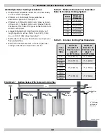
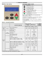
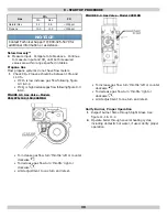
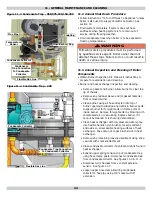
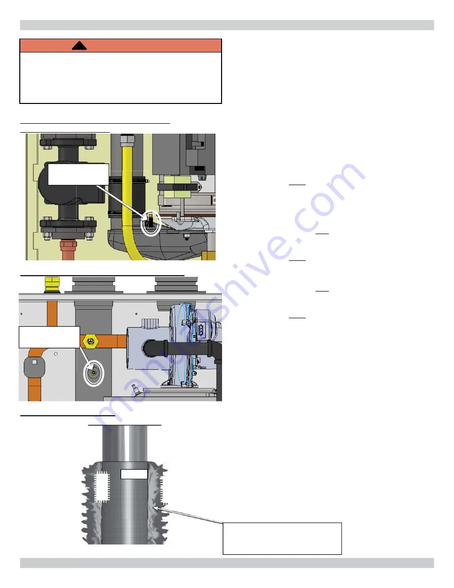
FIGURE 9-5 Combustion Analyzer Port -
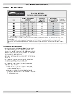
050/075/100/150/200
Flame
Flame
Burner
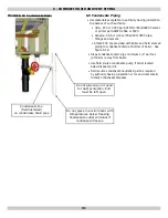
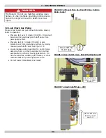
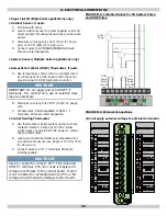
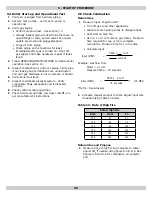
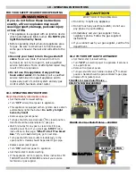
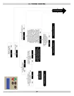
9.6 Perform CSD-1 Compliance Test (see
paragraph 2.4 page 6)
Verify operation of boiler safety control operation with
regard to no
fl
ow conditions as follows:
1.
Turn off boiler using boiler service switch.
2.
Disable primary boiler pump. Disconnect multi pin
connector J7 from control module. See
fi
gure 9-8.
3.
Disable secondary system pumps attached to
system.
4.
Establish call for heat. Jump CHW T-T terminals
on low voltage terminal block. Turn on boiler using
boiler service switch.
5.
Boiler will
fi
re. Based on natural convection within
boiler, boiler will either:
A. Lockout A-06 "Safety Relay Error". Requires
manual reset of control module. Press reset
button on User interface. See
9.3 Program Boiler
Control
.
OR
B. Shut off burner E40 "Return Water Temp". This
is a soft lockout. When water temperature drops
below limit boiler will automatically re
fi
re then
Lockout A-06 requiring manual reset of control
module. Press Reset button on User Interface.
OR
C. Shut off burner E39 "Flue Temperature Sensor".
This is a soft lockout. When
fl
ue sensor drops
below limit, boiler will automatically re
fi
re then
Lockout A-06 requiring manual reset of control
module. Press Reset button on User Interface.
6.
After safety operation is veri
fi
ed, turn off boiler via
service switch. Remove jumper in T-T. Replace J7
connector into control module, enable secondary
pump operation, turn service switch on and restart
system to verify operation.
Combustion
Analyzer Port
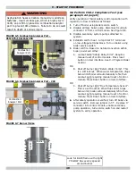
WARNING
Asphyxiation hazard. Carbon monoxide is odorless,
tasteless, clear colorless gas, which is highly toxic.
Verify cap is
fi
rmly placed on combustion analyzer
port to prevent CO emission. Failure to do so could
result in death or serious injury.
!
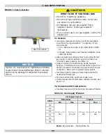
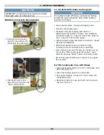
FIGURE 9-7 Burner Flame
Look for BLUE
fl
ame with slight
YELLOW tips evenly spaced
around burner
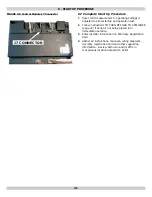
FIGURE 9-6 Combustion Analyzer Port - 299
Combustion
Analyzer Port
9 - START UP PROCEDURE
Содержание Olsen OLSSC-299
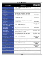
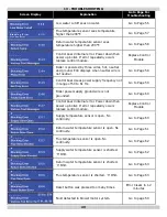
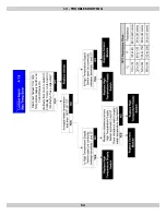
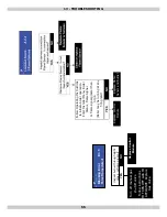
Страница 47: ...47 13 TROUBLE SHOOTING ...
Страница 51: ...51 13 TROUBLE SHOOTING ...
Страница 53: ...53 13 TROUBLE SHOOTING ...
Страница 62: ...62 Supply Water Temperature Sensor Resistance Chart 13 TROUBLE SHOOTING ...
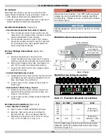
Страница 66: ...66 14 3 Connection Diagram 299 MBH 14 WIRING DIAGRAM EXTERNAL PUMP RELAY LIMIT OF 1 AMP PER PUMP SEE SECTION 8 ...
Страница 84: ...ECR International Inc 2201 Dwyer Avenue Utica NY 13501 web site www ecrinternational com ...


