background image

18

5

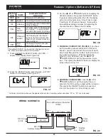
CHEMICAL FEEDER TIME:

Use the 

p

UP or 

q

DOWN buttons to set the length of time, in 

seconds, that the auxiliary output will be turned on.

Then press the SELECT button to accept and

return to the normal run (time of day) screen.

ECOWATER

S Y S T E M S

Features / Options (Softeners & Filters)

SELEC-

TION

NAME

AUXILIARY OUTPUT

FUNCTION

OFF

Off

Remains off indefinitely.

BP

Bypass

On during the entire recharge.

CL

Chlorine

On during the brine draw portion

of the recharge.

FS

Flow

Switch

On when water is flowing past

the turbine*.  It will shut off 8

seconds after water flow stops.

CF

Chemical

Feeder

After the set volume of water

has flowed past the turbine*,

turns on for the time set (see

Steps 4 & 5, below, to set vol-

ume and time).

FR

Fast

Rinse

On during the fast rinse por-

tion of the recharge.

The default is OFF.  If you wish to change to one of

the other selections shown in the table:

1

. Press and hold the SELECT button until “000 - -”

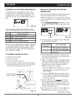
shows in the display (See Figure 36).

3

. Use the 

p

UP or 

q

DOWN buttons to display the

desired selection, then press the SELECT button.

If you selected anything other than CF, the display

will return to the normal run (time of day) screen.

If setting to CF (Chemical Feeder), there will be

two additional settings to make for operating the

chemical feeder in Steps 4 and 5, below.

FIG. 37

FIG. 38

FIG. 39

4

CHEMICAL FEEDER TRIP VOLUME:

If you have

set the auxiliary output control to CF (Chemical

Feeder), you will need to set the volume of water

which must flow past the turbine* before the auxil-

iary output is turned on.  With the alternating

screens in Fig. 38 shown, use the 

p

UP or 

q

DOWN buttons to set the trip volume, in gal-

lons.  Then press the SELECT button to display the

screen shown in Fig. 39.

FIG. 36

2

. Press the SELECT button several times, until “Ctrl"

flashes in the display (See Figure 37).

WIRING SCHEMATIC

FIG. 40

NO

Valve

Motor

Position

Switch

NC

Power Supply

Back of Electronic Controller

(PWA)

Power

In

Pos./Turbine

Motor

24V DC

Auxiliary Output

J4

24V DC

120V AC 

60 Hz

C

org

grn

*

A turbine and turbine cable must be added to the system if auxiliary output selections “FS” or “CF” are to be used.

Содержание ESS1152XR32

Страница 1: ...St Paul MN 55164 0420 www ecowater com Designed Engineered Assembled in the U S A System tested and certified by the Water Quality Association against CSA B483 1 System tested and certified by NSF International against NSF ANSI Standard 44 for hardness reduction and certified to NSF ANSI Standard 372 7368205 Rev B 8 31 18 Model ESS1152XR32 ...

Страница 2: ...te disinfection before or after the system European Directive 2002 96 EC requires all electrical and electronic equipment to be disposed of according to Waste Electrical and Electronic Equipment WEEE require ments This directive or similar laws are in place nationally and can vary from region to region Please refer to your state and local laws for proper disposal of this equipment Follow the insta...

Страница 3: ...roduct This warranty is called the Perfect Ten and extends the three year warranty on the electronic FACE PLATE WIRING HARNESS DRIVE MOTOR POWER SUPPLY POWER CORD SENSOR HOUSING and MICRO SWITCH ES to a total of TEN YEARS from the date of original installation Your local dealer will provide details regarding this warranty or will refer you to the factory for additional information Should your loca...

Страница 4: ... Intermittent flow rate does not represent the maximum service flow rate used for determining the unit s rated capacity and efficiency Continuous operation at flow rates greater than the service flow rate may affect capacity and efficiency performance Capacity to remove clear water iron is substantiated by independent laboratory test data State of Wisconsin requires additional treatment if water s...

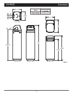
Страница 5: ...14 39 1 4 34 1 4 IN OUT 49 9 16 3 3 8 IN OUT 57 5 14 1 4 FIG 1 IN OUT 49 9 16 Model Nominal Resin Tank Size ESS1152XR32 10 dia x 47 SIDE VIEW FRONT VIEW TOP VIEW IN OUT BRINE TANK 39 3 8 34 1 4 20 14 13 5 8 3 3 8 57 ECOWATER S Y S T E M S Dimensions ...

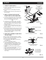
Страница 6: ...ENER To soften all water in the home install the water softener close to the water supply inlet upstream of all other plumbing connections except outside water pipes Outside faucets should remain on hard water to conserve salt and softening capacity Place the softener near a floor drain or other acceptable drain point laundry tub sump stand pipe etc to carry away regeneration discharge water Conne...

Страница 7: ...used and media in that order Be sure the distributor remains centered Use water sparingly to speed flow through the funnel It may become necessary to siphon water from the bottom of distributor if tank becomes full of water 8 Flush the tank opening with water to clean media particles from the top of the tank Uncover the bot tom distributor riser pipe 9 Finish filling the tank with water up to the ...

Страница 8: ...WATER FROM SOFTENER OUTLET Hard Water to Outside Faucets EcoWater Bypass Valve CONNECTING A RIGID VALVE DRAIN TUBE Compression Fitting 1 4 NPT x 1 2 O D Tube not included Clip Barbs 1 4 NPT Threads 1 2 Outside Dia Copper Tube not included Cut barbs from drain fitting pull clip to remove fitting from valve 120V 60 Hz Outlet INLET OUTLET INLET OUTLET Do not connect the water softener valve drain hos...

Страница 9: ...y in place 3 COMPLETE PLUMBING TO AND FROM THE SOFTENER Using the Typical Installation Illustration on page 8 as a guide observe all of the following cautions while you connect inlet and outlet plumbing Be sure incoming hard water is directed to the valve INLET port Be sure to install bypass valve s If making a soldered copper installation do all sweat soldering before connecting pipes to the fil ...

Страница 10: ... drain fitting securing it with a hose clamp See Figure 6 on page 8 b Locate the other end of the hose at a suitable drain point floor drain sump laundry tub etc Check and comply with local codes Refer to Figure 6 on page 8 if codes require a rigid pipe drain run IMPORTANT Use high quality thick wall hose that will not easily kink or collapse The softener will not backwash properly if water cannot...

Страница 11: ...ve is in the bypass position h Plug in the power supply i Program the electronic controller Follow the steps on Pages 13 14 for softeners or Page 16 for filters to program the electronic controller with basic operating information such as time and water hardness After completing these steps continue with j Start a recharge below j Start a recharge Press the RECHARGE button and hold for 3 seconds u...

Страница 12: ... softener begins recharging This recharge draws the sanitizing bleach into and through the softener Any air remaining in the unit is purged to the drain d After the recharge has completed fully open a cold water faucet downstream from the softener and allow 50 gallons of water to pass through the sys tem This should take at least 20 minutes Close the faucet 12 RESTART THE WATER HEATER Turn on the ...

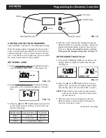
Страница 13: ...esent time Up moves the display ahead down sets the time back Be sure AM or PM is correct NOTE Press buttons and quickly release to slowly advance the display Hold the buttons down for fast advance 3 When the correct time is displayed press the SELECT button and the display will change to show the Hardness screen continued on next page 4 With the correct model code displayed press the SELECT butto...

Страница 14: ...es SET NUMBER OF PEOPLE If a hardness level was set in the previous step you will set the Number of People in the household 1 Press the p UP or q DOWN buttons to set the number of people The factory default is 4 2 When the correct number of people is displayed press the SELECT button and the display will change to show the Set Recharge Time screen 1 Press the p UP or q DOWN buttons to set the numb...

Страница 15: ... in the display 2 Press the SELECT button four times and bA will appear in the display followed by the current back wash time in minutes flashing 3 Use the p UP or q DOWN buttons to set the number of minutes desired for backwash 4 Press the SELECT button again and Fr will appear in the display followed by the current fast rinse time in minutes flashing 5 Use the p UP or q DOWN buttons to set the n...

Страница 16: ...n the correct time is displayed press the SELECT button and the display will change to show the Recharge screen SET DAYS BETWEEN RECHARGES This setting is the number of days the filter will go between recharges The default setting is 2 days with a maximum setting of 99 days 1 If you completed the previous steps the words RECHARGE and day should show in the dis play See Figure 28 Otherwise press th...

Страница 17: ...remaining screens and return to the normal run time of day display ADJUSTABLE FAST RINSE TIME 1 Press and hold the SELECT button until 000 shows in the display 2 Press the SELECT button five times and Fr will appear in the display followed by the current fast rinse time in minutes flashing FIG 34 FIG 35 3 Use the p UP or q DOWN buttons to set the number of minutes desired for fast rinse from 0 to ...

Страница 18: ...re 36 3 Use the p UP or q DOWN buttons to display the desired selection then press the SELECT button If you selected anything other than CF the display will return to the normal run time of day screen If setting to CF Chemical Feeder there will be two additional settings to make for operating the chemical feeder in Steps 4 and 5 below FIG 37 FIG 38 FIG 39 4 CHEMICAL FEEDER TRIP VOLUME If you have ...

Страница 19: ... time of day screen See Fig 41 will then be dis played Remember to do this or the unit will not recharge and you will soon have hard unfiltered water FIG 43 NORMAL OPERATION During normal operation the present time of day shows in the display POWER OUTAGE MEMORY If electrical power to the softener filter s control is lost internal memory will maintain most settings such as the hardness and recharg...

Страница 20: ...ded SALT WITH IRON REMOVING ADDITIVE Some salts have an additive to help a water softener handle iron in the water supply Although this may help keep the resin bed clean it may also release corrosive fumes that will weaken and shorten the life of some EcoWater Systems softener electronic parts Iron Out salt is safe to use on two tank models BREAKING A SALT BRIDGE Sometimes a hard crust or salt bri...

Страница 21: ...ift out the screen support and screen Then remove the nozzle venturi disc gas ket and flow plug Wash the parts in warm soapy water and rinse in fresh water Be sure to clean both the top and bottom of the nozzle venturi disc If needed use a small brush to remove iron or dirt Do not scratch misshape etc surfaces of the nozzle venturi Gently replace all parts in the correct order Lubricate the o ring...

Страница 22: ...e the problem TO REMOVE AN ERROR CODE 1 Unplug the power supply 2 Correct the problem 3 Plug the power supply back in 4 Wait for at least 8 minutes while the timer operates the valve through an entire cycle The error code will return if the problem was not corrected Switch Correct Switch Displays Valve Cycle Status Valve in service fill brining backwash or fast rinse position P Valve rotating from...

Страница 23: ...continued from previous page 7 To return to the present time display press the SELECT button If the model code was changed make all controller settings NOTE If the electronic control is left in a diagnostic display or a flashing display when setting times or hardness present time automatically returns if a button is not pressed within 4 min utes RESETTING TO FACTORY DEFAULTS To reset the electroni...

Страница 24: ...24 ECOWATER S Y S T E M S Repair Parts Valve Assembly See Pages 26 27 for parts 1 6 5 7 9 26 27 23 24 25 28 29 30 31 32 10 22 21 33 4 13 15 14 18 19 20 17 12 8 11 16 SYSTEM EXPLODED VIEW 3 2 ...

Страница 25: ...Nos 16 17 16 á Nut 17 á Screw Key No Part No Description 7331258 Overflow Hose Adaptor Kit includes Key Nos 18 20 18 á Grommet 19 á Adaptor Elbow 20 á Hose Clamp 21 7310210 Brine Valve Assembly 22 7327568 Float Stem Guide Assembly 23 7124415 Gravel 17 lbs Ù 24 0502272 Resin 1 cu ft standard mesh Ù 25 7092202 Resin Tank 10 dia x 47 7331177 Tank Neck Clamp Kit includes 2 ea of Key Nos 26 27 26 á Cla...

Страница 26: ...R S Y S T E M S Repair Parts VALVE EXPLODED VIEW 51 50 52 53 55 56 59 58 57 60 61 66 67 62 63 64 68 69 75 76 65 77 78 80 79 81 82 83 Wear Strip Seal Cross section View 84 85 86 87 88 89 90 54 70 71 72 73 74 91 70 ...

Страница 27: ...tion Nut Ù 2 req 72 0507615 Installation Tube 3 4 Ù 2 req 73 7170335 Washer Ù 2 req Key No Part No Description 74 7278442 Installation Adaptor 3 4 single 2 req 7336606 Installation Adaptor 3 4 pack of 10 includes 10 ea of Key No 75 75 7170288 O Ring 15 16 x 1 3 16 single 2 req 7336402 O Ring 15 16 x 1 3 16 pack of 20 76 7082053 Valve Body 77 7081201 Retainer Nozzle Venturi 78 7170319 O Ring 1 4 x ...

Отзывы: