background image

7

ECOWATER

S Y S T E

M S

Installation

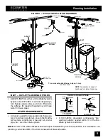
5. CONNECT INLET AND OUTLET PLUMBING

a.

SOLDERED COPPER

(1) Thoroughly clean and flux all joints.
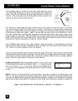
(2) Pull the plastic ‘‘C’’ clips and remove the inlet and

outlet tubes from the valve. Remove o--rings from

the tubes.

DO NOT solder with tubes in the valve.

Soldering heat will damage the valve.

NOTE

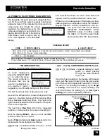
: If installing a ground as shown in FIGURE

4A,

place hose clamps on copper tubes before

soldering

(see step 6a).

(3) Make all solder connections. Be sure to keep fit-

tings fully together, and pipes square and straight.

b.

THREADED PIPE

(1) Apply pipe joint compound to all outside pipe

threads.
(2) Tighten all threaded joints.
(3) If soldering to the inlet and outlet tubes, observe

step

a

above.

c.

CPVC PLASTIC PIPE

(1) Clean, prime and cement all joints, following the

manufacturer’s instructions supplied with the plastic

pipe and fittings.
(2) If soldering to the inlet and outlet tubes, observe

step

a

above.

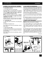
6. COLD WATER PIPE GROUNDING

The house cold water pipe (metal only) is often used

as a ground for the house electrical system. The

3-valve bypass type of installation, shown in FIG-

URE 1, will maintain ground continuity. If you use the

plastic bypass, continuity is broken. To restore the

ground, do either step

a

or

b

following.

a.

Use the included gound clamp kit to make a jump-

er across the inlet and outlet copper tubes, FIGURE

4A.

b.

Install a #4 copper wire across the removed sec-

tion of main water pipe, securely clamping at both

ends, FIGURE 4B (parts not included).

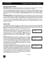
7. INSTALL VALVE DRAIN HOSE

NOTE

: See valve drain options on page 5.

a.

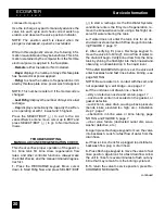
Connect a length of 1/2” I.D. hose (check codes)

to the valve drain elbow, on the controller. Use a

hose clamp to hold the hose in place. Route the

hose out through the notch in the back of the top

cover.

b.

Run the hose to the floor drain, and as typically

shown in FIGURE 1, tie or wire the end to a brick or

other heavy object. This will prevent ‘‘whipping’’ dur-

ing regenerations. Be sure to provide a 1--1/2” mini-

mum air gap, to prevent possible sewer water back-

up.

continued

ground wire

clamp (2)

nozzle &

venturi

o--ring

elbow

FIGURE 4

FIGURE 5

FIGURE 6

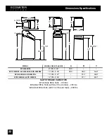
Note: To ease brine tubing con-

nection, use the elbow and o--ring

seal as shown. Lubricate the o--

ring and insert into the elbow. Turn

the elbow on and tighten. Then,

back--off up to one turn, as need-

ed.

B

A

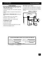
3 -- Valve Bypass

OUTLET

VALVE

INLET

VALVE

BYPASS

VALVE

to conditioner

from conditioner

EcoWater Systems

Bypass Valve

D

for

SERVICE:

-- Open

the

inlet

and

outlet

valves.

-- Close

the

bypass valve.

D

for

BYPASS:

-- Close

the

inlet

and

outlet

valves.

-- Open

the

bypass valve.

PUSH

IN

for

bypass

PULL

OUT

for

service

nut--ferrule

screen

ground

clamp

brine

tubing

Содержание ECR 3000R20

Страница 1: ...SERIES 3000 3002 R P N 7283586 cut along dotted line to remove torn outer cover...

Страница 2: ...oWater Systems Conditioner with Remote ECR EcoWater Systems Refiner with Remote ERR SERIES 3000 3002 R ERR 3000R20 ERR 3002R30are Tested and Certi fied by NSF International and WQA against NSF ANSI St...

Страница 3: ...ner where freezing temperatures occur Do not attempt to treat water over 120 F Freezing or hot water damage voids the warranty Avoid installing in direct sunlight Excessive sun heat may cause distorti...

Страница 4: ...ed the water conditioner is operated at water pressures not exceeding 125 psi and at water temperatures not exceeding 120 F and on a municipal chlorinated water supply models designated as ERR on the...

Страница 5: ...of the contents a Ferrous clear water iron is soluble and dis solves in water It is usually detected by taking a sample of waterin a clear bottle or glass Immediate ly after taking the sample is clear...

Страница 6: ...NG OPTIONS S ALWAYS INSTALL either an EcoWater Systems bypass valve 7214383 or a 3 valve bypass sys tem Bypass valves allow you to turn off water to the softener for repairs if needed but still have w...

Страница 7: ...ear the well pump or water meter b Shut off the electric or fuel supply to the water heater c Open high and low faucets to drain all water from the house pipes 3 INSTALLING THREE VALVE BYPASS If insta...

Страница 8: ...step a or b following a Use the included gound clamp kit to make a jump er across the inlet and outlet copper tubes FIGURE 4A b Install a 4 copper wire across the removed sec tion of main water pipe...

Страница 9: ...not infect or contaminate your water supply and will not cause bacteria to form or grow However during shipping storage installing and operating bacteria could get into the unit For this reason sanit...

Страница 10: ...ss to move the display ahead press to move the time backward NOTE Each press of a keypad changes the time by 1 min ute Holding a keypad in changes the time by 32 minutes each second Pressing the SELEC...

Страница 11: ...red LED flashes twice every 3 seconds the re mote is out of range of signal and needs to be re positioned Press SELECT EXIT to exit to the Advanced Service Menu Move square cursor J to EXIT and press...

Страница 12: ...ou reset the controller to the correct time of day To reset present time see step 2 on page 9 CONTROL FEATURES There are three keypads on the left side of the display SaltLev el keypad is used when ad...

Страница 13: ...quare cursor J to EXIT which appears at either the top or the bottom of this menu If no keypad has been pressed display will show for 4 minutes before returning back to the Normal Screen Views Set Clo...

Страница 14: ...ss the SELECT EXIT keypad This screen is similar to a trip odometer in that it will count the number of gallons liters through the system until it is reset To reset back to zero press the keypad Set R...

Страница 15: ...Spanish or French Test Remote Press the or keypads until cursor is next to Test Re mote and press SELECT EXIT At set up the unit will send a signal to the remote every 3 seconds to allow for correct...

Страница 16: ...this feature is changed it will delete all information stored in the controller Hardness Recharge time will have to be reset All usage history will be cleared When you are certain the correct code app...

Страница 17: ...ck of remote The EcoWater Systems remote uses 3 AAA batteries which are included To check batteries press reset button on back of remote monitor If batteries are good the LED s on the remote should sc...

Страница 18: ...e bridge is under it Take a broom handle or like tool and push it straight down into the salt If a hard object is felt it s most likely a salt bridge Carefully push into the bridge in several places t...

Страница 19: ...t time of day If display is blank check power source to the Eco Water Systems conditioner If time is incorrect power was off for over 2 days The conditioner resumes normal operation when power returns...

Страница 20: ...d TROUBLESHOOTING MANUAL INITIATED ELECTRONIC DIAGNOSTICS To enter diagnostics press the SELECT EXIT to enter the menu This screen contains in formation that can be used to troubleshoot er rors Use th...

Страница 21: ...the EcoWater Systems conditioner enters the fill cycle of regeneration re move the brinewell cover and using a flashlight ob serve fill water entering the tank a If water does not enter the tank look...

Страница 22: ...tive valve seals 3 Restricted or plugged backwash fast rinse controls 4 Restricted or plugged drain line WATER HAS SALTY TASTE 1 House water pressure low adjust pump if well system 2 Partially restric...

Страница 23: ...SIZE A B C ECR 3000R20 8 DIA X 35 39 5 ECR 3000R30 ECR 3002R30 ERR 3000R20 10 DIA X 35 39 5 39 5 44 8 ECR 3002R40 ERR 3002R30 10 DIA X 47 51 3 56 6 ECR 3002R50S ECR 3002R70 12 DIA X 54 57 1 62 2 SALT...

Страница 24: ...n Max Working Pressure psi z 20 125 Min Max Operating Temperature _F 40 120 Min Water Supply Flow Rate gpm 3 Max Flow Rate gpm to Drain During Regeneration Cycle 2 4 3 0 3 0 3 0 3 0 5 4 5 4 Y Efficien...

Страница 25: ...2 33 34 35 36 37 11 12 13 14 15 16 19 20 28 24 22 23 22 23 30 21 18 19 20 29 38 40 41 42 14 45 43 1 2 3 4 6 46 39 5 26 27 44 25 17 18 21 24 ECOWATER S Y S T E M S Repair Parts ECOWATER SYSTEMS CONDITI...

Страница 26: ...t 23 1103200 Hose Adaptor 7112882 Hose Clamp not shown 24 7218604 Brine Tank Cabinet 25 7218696 Light Assembly includes o ring and nut KEY NO PART NUMBER PART DESCRIPTION 26 7274210 Rim Cabinet 27 721...

Страница 27: ...OWATER S Y S T E M S Repair Parts VALVE ASSEMBLY 1 2 3 4 6 7 8 9 10 11 12 13 14 15 16 17 18 19 20 16 21 22 23 24 25 26 27 28 29 30 31 33 32 34 35 36 37 38 39 13 40 14 41 42 43 44 45 46 47 48 49 50 51...

Страница 28: ...black Gasket Kit ECR 3000R20 ERR 3000R20 ECR 3000R30 ECR 3002R30 ERR 3002R30 ECR 3002R40 7114533 Nozz Vent blue Gasket Kit ECR 3002R50S ECR 3002R70 7204362 Gasket only black KEY NO PART NO PART DESCRI...

Страница 29: ...ECOWATER S Y S T E M S 3 R EcoWater Systems PO Box 64420 St Paul MN 55164 9888 1 800 86WATER...

Отзывы: