
09.06.2017 Rev. 08
59
MAINTENANCE
Weekly Maintenance
Weekly maintenance is a routine cleaning and adjustment procedure which is performed to ensure
smooth and continuous operation of the system. Burner components must be adjusted after each
maintenance work in accordance with the instructions. Otherwise, the burner cannot be operated
efficiently.
Ø
Clean all filters in fuel ring system.
Ø
Clean fuel nozzle of the burner.
Ø
If the fin spaces and surface of the diffuser are covered with particles and formed a layer, clean it
with a wire brush.
Ø
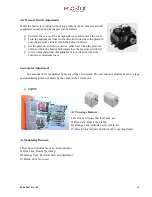
Clean heads of ignition electrodes. Check by performing manual ignition, adjust the distance
between the ignition electrode and diffuser according to the adjustment instructions.
Monthly Maintenance
Monthly maintenance is a more comprehensive maintenance compared to weekly maintenance,
where general checks of burner and peripheral components are performed to prevent possible faults. After
completion of maintenance and adjustment processes, make sure to perform a combustion analysis.
Ø
Clean the filters on the fuel line to the burner.
Ø
Clean fuel nozzle of the burner.
Ø
Clean the surface of the diffuser.
Ø
Clean flame pipe.
Ø
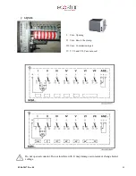
Check all wiring points. Tighten loose connections.
Ø
Clean the solenoid valves.
Ø
Clean the photocell.
Ø
Clean the dust and layers accumulated on the fan and air valves.
Ø
Check pump pressure. Check if necessary (Light Oil: Two stage 14 bar, modulating; 25 bar)
Ø
Check ignition electrodes. Adjust it if necessary. Check ignition cables and sockets.
Ø
Perform cleanliness control of inside panel. Clean if necessary.
Ø
Check all bolts of the burner. Tighten loose bolts.
Ø
Clean the filters on the main line and multiblock.
Ø
Check the burner gas tip.
Ø
Check gas line pressure, it must be the same with the first adjusted pressure, otherwise burner load
and emission values will also have changed.
Ø
After starting the burner and adjusting air klappe, perform flue gas analysis and check if there is
an ideal combustion.
Содержание ECO 50 K L C 2
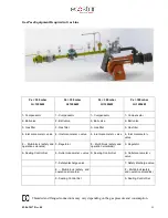
Страница 10: ...09 06 2017 Rev 08 9 Burner Components ECO 50 KLC2...
Страница 12: ...09 06 2017 Rev 08 11 ECO 55 KLC2 2a...
Страница 14: ...09 06 2017 Rev 08 13 ECO 60 KLC2...
Страница 16: ...09 06 2017 Rev 08 15 ECO 65 KLC2...
Страница 18: ...09 06 2017 Rev 08 17 ECO 70 KLC2...
Страница 20: ...09 06 2017 Rev 08 19 ECO 50 KLC3...
Страница 22: ...09 06 2017 Rev 08 21 ECO 55 KLC3 3a...
Страница 24: ...09 06 2017 Rev 08 23 ECO 60 KLC3...
Страница 26: ...09 06 2017 Rev 08 25 ECO 65 KLC3...
Страница 28: ...09 06 2017 Rev 08 27 ECO 70 KLC3...
Страница 30: ...09 06 2017 Rev 08 29 ECO 75 KLC3...
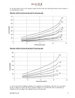
Страница 33: ...09 06 2017 Rev 08 32 Back Pressure Capacity Diagrams...
Страница 34: ...09 06 2017 Rev 08 33 Burner Dimensions...
Страница 36: ...09 06 2017 Rev 08 35...
Страница 37: ...09 06 2017 Rev 08 36...
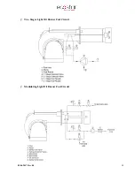
Страница 46: ...09 06 2017 Rev 08 45 Two Stages Light Oil Burner Fuel Circuit Modulating Light Oil Burner Fuel Circuit...
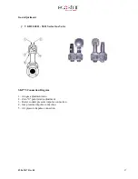
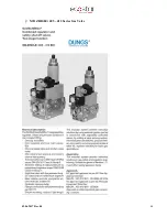
Страница 49: ...09 06 2017 Rev 08 48 MB ZRD LE 405 412 Series Gas Valve...
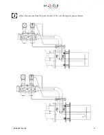
Страница 56: ...09 06 2017 Rev 08 55 If the value measure from PL point is below 0 5 bar set the impulse pipe as follows...
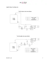
Страница 58: ...09 06 2017 Rev 08 57 Light Oil Burner Fuel Ring Line...


