


09.06.2017 Rev. 08
42
Operating with Gas ;
Operation of two-stage burner
Ø
Open the main gas valve, check the gas pressure from the manometer at the valve. (max.300
mbar)
Ø
Check the boiler thermostat or pressure switch settings.
Ø
Bring the operating switch on the burner panel to position 2.
Ø
Burner fan motor will be activated.
Ø
Ignition will take place at the end of pre-purge process.
Ø
3 sec. later, the gas valve will be opened and combustion will occur.
Ø
Flame control system (ionization) will start flame control.
Ø
Burner will switch to the second stage (max. capacity) according to the heat requirement.
Ø
After the boiler water heated up or the boiler pressure has risen, the burner will turn off.
Operation of a modulating burner
Ø
Open the main gas valve; check max 300 mbar gas pressure from the manometer.
Ø
Open operating switch on the burner panel.
Ø
Switch on the modulating control switch.
Ø
Switch automatic-hand switch to automatic.
Ø
Check the temperature and pressure set values from the modulating control unit.
Ø
Ignition will take place at the end of pre-purge process.
Ø
3 sec. later, the gas valve will be opened and combustion will occur.
Ø
Flame control system (ionization) will start flame control.
Ø
In modulating burner, the burner goes into max. capacity according to the signal from the
modulating control unit.
Ø
When the boiler water temperature or steam pressure increase, the modulating control unit will
cause burner to run with min. capacity.
Ø
If the boiler water temperature or steam pressure increases despite the operation of burner with
min. capacity, the modulating control unit will stop the burner.
Содержание ECO 50 K L C 2
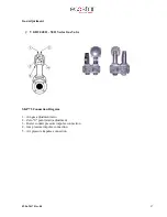
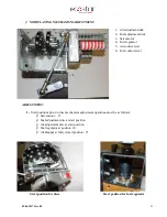
Страница 10: ...09 06 2017 Rev 08 9 Burner Components ECO 50 KLC2...
Страница 12: ...09 06 2017 Rev 08 11 ECO 55 KLC2 2a...
Страница 14: ...09 06 2017 Rev 08 13 ECO 60 KLC2...
Страница 16: ...09 06 2017 Rev 08 15 ECO 65 KLC2...
Страница 18: ...09 06 2017 Rev 08 17 ECO 70 KLC2...
Страница 20: ...09 06 2017 Rev 08 19 ECO 50 KLC3...
Страница 22: ...09 06 2017 Rev 08 21 ECO 55 KLC3 3a...
Страница 24: ...09 06 2017 Rev 08 23 ECO 60 KLC3...
Страница 26: ...09 06 2017 Rev 08 25 ECO 65 KLC3...
Страница 28: ...09 06 2017 Rev 08 27 ECO 70 KLC3...
Страница 30: ...09 06 2017 Rev 08 29 ECO 75 KLC3...
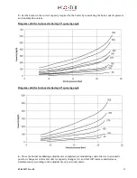
Страница 33: ...09 06 2017 Rev 08 32 Back Pressure Capacity Diagrams...
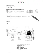
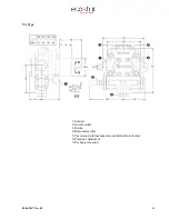
Страница 34: ...09 06 2017 Rev 08 33 Burner Dimensions...
Страница 36: ...09 06 2017 Rev 08 35...
Страница 37: ...09 06 2017 Rev 08 36...
Страница 46: ...09 06 2017 Rev 08 45 Two Stages Light Oil Burner Fuel Circuit Modulating Light Oil Burner Fuel Circuit...
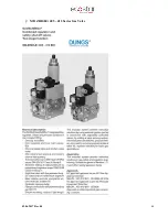
Страница 49: ...09 06 2017 Rev 08 48 MB ZRD LE 405 412 Series Gas Valve...
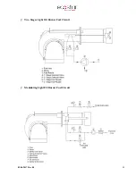
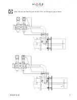
Страница 56: ...09 06 2017 Rev 08 55 If the value measure from PL point is below 0 5 bar set the impulse pipe as follows...
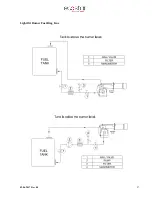
Страница 58: ...09 06 2017 Rev 08 57 Light Oil Burner Fuel Ring Line...


