background image

 User manual ecoSMART 

e-system


64 


EN


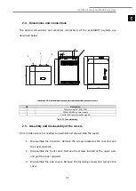
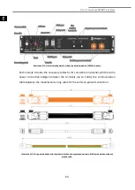
Illustration 3.11. Front view and parts of a lithium-ion battery module of 2.4kWh capacity. 

Each module includes the necessary cables for its connection in parallel, which are the 

power  connection  bridges  between  the  terminals  (up  to  120A),  the  communication 

cable between the modules and a long cable for the common ground connection. 

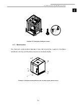
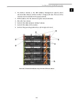
Illustration 3.12. Wiring pack included with the module: Positive and negative power cable, RJ45 communication cable and 

ground cable. 


Содержание e-system

Страница 1: ...MANUAL INSTALADOR INSTALLER MANUAL INSTALLERHANDBUCH MANUEL DE INSTALLATION INSTALLATIE HANDLEIDING ES EN DE FR NL 07 2018 SOFTWARE VERSION v03 ecoSMART e system MODEL SERVICE CONTACT ...

Страница 2: ......

Страница 3: ...TRICA 10 3 1 INSTRUCCIONES GENERALES 11 3 2 ENTRADA DE CAMPO FV 12 3 3 CONEXIÓN DE RED 13 3 4 SALIDA EPS 14 3 5 ALIMENTACIÓN ELÉCTRICA DEL CONTROL 16 3 6 PUERTOS DE COMUNICACIÓN PLAN FIELDBUS1 BMS2 16 3 7 ENTRADAS DIGITALES DE CONTROL DIXX 17 3 8 SALIDAS DIGITALES A RELÉ DOXX 18 3 9 INSTALACIÓN O REEMPLAZO DE LOS MÓDULOS 19 4 PUESTA EN MARCHA 24 4 1 CONFIGURACIÓN DEL INVERSOR SOLAR 25 4 2 ACTUALIZ...

Страница 4: ...13 MENÚ CONTROL DE EXCEDENTE 35 5 14 MENÚ CONTROL DE CONSUMO 36 5 15 MENÚ CONTROL DE TARIFA 36 5 16 MENÚ MODOS SG 37 5 17 MENÚ ACTIVACIÓN MANUAL 37 5 18 MENÚ REGISTRO DE ALARMAS 38 5 19 MENÚ VALORES POR DEFECTO 38 6 SÍMBOLOS 39 7 ALARMAS Y SOLUCIÓN DE PROBLEMAS 40 7 1 ALARMAS ACTIVAS 40 8 ESPECIFICACIONES TÉCNICAS 41 9 GARANTÍA Y SERVICIO TÉCNICO 43 9 1 GARANTIA DE FABRICANTE 43 9 2 DISTRIBUIDORES...

Страница 5: ...riales o un mal funcionamiento del equipo También puede servir para indicar prácticas recomendables o no recomendables para el equipo PELIGRO Alerta de una situación de peligro inminente o en potencia que si no se evita puede causar lesiones o incluso la muerte También puede servir para alertar de prácticas no seguras El equipo ecoSMART e system ha sido diseñado para ser utilizado con bombas de ca...

Страница 6: ... resolverlo No toque ninguno de los componentes internos durante o inmediatamente después de su funcionamiento Usted debe desconectar completamente el equipo y aislarlo de todos los circuitos eléctricos antes cualquier manipulación o trabajo de mantenimiento Instale un DDR dispositivo diferencial residual en cada línea de corriente alterna que salga del sistema Los DDR deben de ser de tipo cuadrip...

Страница 7: ... mantenimiento específico tras la puesta en marcha El controlador interno monitoriza constantemente numerosos parámetros y le indicará si ocurre algún problema o incidencia en cuyo caso le recomendamos se ponga en contacto con su distribuidor PELIGRO Todos los trabajos de mantenimiento deben ser realizados por un técnico autorizado Una manipulación inadecuada de la instalación en su conjunto puede...

Страница 8: ...inactividad los módulos de la batería se descargarán automáticamente al nivel mínimo de energía en un proceso que puede dañar irreversiblemente las baterías Por esta razón los módulos de batería no deben almacenarse durante más de seis meses sin uso y siempre bajo las siguientes condiciones Cada módulo de batería debe almacenarse con un nivel de carga igual o superior al 90 de la capacidad nominal...

Страница 9: ...ido del e system 2 4 Dimensiones y conexiones Las dimensiones generales y las conexiones eléctricas del ecoSMART e system se describen a continuación Ilustración 2 2 Dimensiones totales y conexiones eléctricas datos en mm Tornillos de anclaje 90 1058 720 70 970 710 4x 507 45 3x 9 x Ø 4 5 8 5 1 2 3 ...

Страница 10: ... carcasa 1 Desmontar la cubierta superior Retire los tornillos ubicados en la parte posterior y tire de la tapa hacia arriba 2 Desmontar la cubierta frontal Retire los tornillos ubicados en la parte superior y tire de la cubierta hacia arriba 3 Desmontar las cubiertas laterales Retire los tornillos de fijación y retire la tapa Ilustración 2 2 Desmontaje de las cubiertas del e system NOTA Durante e...

Страница 11: ... de las baterías Use las patas ajustables para compensar posibles irregularidades en la superficie de soporte Ilustración 2 3 Posicionamiento y nivelado del e system 2 7 Área de servicio Las distancias mínimas recomendadas alrededor del e system para facilitar la instalación puesta en marcha y los trabajos de mantenimiento se indican a continuación Ilustración 2 4 Área de servicio mínima recomenda...

Страница 12: ...positivo diferencial residual en cada línea de corriente alterna que salga del sistema Los DDR deben de ser de tipo cuadripolar con una corriente residual máxima igual a 300mA clase A Si usted no puede estar completamente seguro de que el equipo se encuentra aislado de los elementos activos de la instalación es altamente recomendable ejecutar mediciones eléctricas para comprobar que todas las part...

Страница 13: ...e la instalación además de las conexiones eléctricas y de la comunicación con la bomba de calor puede ser necesario conectar señales de control externas entradas digitales DIxx activación desactivación de cargas no críticas salidas digitales DOxx o incluso comunicación con otros dispositivos externos puerto BMS2 Bloque DIxx Entradas digitales Interruptor principal Salida EPS Alimentación eléctrica...

Страница 14: ...pasar los 12A Terminal CC Sección cable Corriente máxima Polo positivo rojo 6 mm2 25 A Polo negativo negro 6 mm2 25 A Tabla 1 1 Dimensionado de los cables de potencia y los interruptores externos de las ramas FV Inserte los cables provenientes de los campos fotovoltaicos a través de la tapa trasera en la esquina superior izquierda del e system y conectarlos como se muestra en la figura Ilustración...

Страница 15: ...nto de los cables y el interruptor externo de la conexión de red Es imprescindible instalar el sensor de corriente CT incluido con el e system para poder determinar las demandas de potencia de las cargas conectadas Pasos para la conexión 1 Coloque el sensor de corriente alrededor del cable de fase L proveniente del cuadro general para medir la potencia inyectada o consumida de la red 2 Asegúrese d...

Страница 16: ...acerlo correctamente u ocurrirá un error 3 4 Salida EPS El cuadro eléctrico del e system también incluye una conexión EPS Emergency Power Supply para asegurar energía de respaldo para ciertas cargas en caso de desconexión de la red eléctrica A través de un potente inversor híbrido en su interior el e system puede utilizar la energía producida directamente en los paneles fotovoltaicos así como la e...

Страница 17: ... el interruptor externo de la conexión EPS Será necesario instalar un interruptor conmutador externo para alternar entre la conexión de red y la salida EPS del e system En la siguiente figura se muestran dos diagramas de conexión de la salida EPS en función de las diferentes directivas locales de conexión eléctrica Ilustración 3 7 Diagramas de conexión salida EPS ...

Страница 18: ... del control puede tomarse directamente del cuadro mediante la conexión a la ficha doble de red o bien por medio de una conexión independiente En este caso inserte el cable de alimentación a través de la cubierta posterior del e system A continuación conecte los cables al bloque de terminales de alimentación como se indica en la imagen Ilustración 3 7 Alimentación para controlador y electrónica en...

Страница 19: ...xión no es necesaria para el correcto funcionamiento del sistema En caso de que usted quiera conectar un dispositivo externo a su ecoSMART e system contacte con el servicio técnico de ECOFOREST en primer lugar 3 7 Entradas digitales de control DIxx El ecoSMART e system permite cablear cuatro entradas digitales para la desconexión remota de cargas no críticas de DI1 a DI4 y dos entradas digitales p...

Страница 20: ...entrada SG1 en modo SG Entrada digital Señal libre de voltaje DI6 Estado de la entrada SG2 en modo SG Entrada digital Señal libre de voltaje DI7 Tabla 4 4 Descripción de las entradas digitales 3 8 Salidas digitales a relé DOxx El programa del controlador permite gestionar hasta cuatro cargas no críticas cuando tenemos excedente eléctrico Los cuatro relés que habilitan estas cargas están incluidos ...

Страница 21: ...ío a través de la regulación de la bomba de calor que se comunica con el sistema como directamente en los módulos de baterías de ión litio que incorpora El sistema de acumulación en baterías consiste en un sistema modular que permite la conexión en paralelo de hasta cinco módulos de 2 4kWh de capacidad cada uno esto es un máximo de 12kWh de capacidad Por defecto el ecoSMART e system es distribuido...

Страница 22: ...ión 3 11 Vista frontal y partes de un módulo de batería de iones de litio de 2 4kWh de capacidad Cada módulo incluye los cables necesarios para su conexión en paralelo es decir los puentes de conexión de potencia hasta 12A el cable de comunicación entre módulos y un cable largo para la conexión común a tierra Ilustración 3 12 Paquete de cableado incluido con el módulo Cable de alimentación positiv...

Страница 23: ...esto de módulos se instalarán en los cajones superiores 2 Coloque la batería en el cajón empleando los agarres laterales 3 Atornille los 4 tornillos pcs 4 Conecte los cables entre los módulos de baterías 5 Conecte los cables al inversor 6 Atornille los cables de tierra a la toma común de tierra Ilustración 3 13 Ejemplo de ensamblaje y cableado de una cascada de módulos de iones de litio ...

Страница 24: ...ncienda todos los módulos de baterías y el LED verde de debajo se encenderá Ilustración 3 14 Interruptor de ON OFF y LED de estado Recuerde que el BMS en la parte inferior es el maestro de comunicación y es el único en el que el Link Port 0 debe estar vacío Ilustración 3 15 Conexión entre maestro BMS y modulo esclavo ...

Страница 25: ...e baterías se encuentran siempre bajo tensión Incluso si el sistema de almacenamiento está apagado lo polos de módulos de baterías conservan un potencial cercano a 48Vcc Utilice solamente los cables facilitados los cuales están protegidos frente a contactos directos No utilice piezas metálicas de joyería mientras manipula el Sistema de almacenamiento Si usted no puede estar completamente seguro de...

Страница 26: ...da coloque el selector del inversor en la posición ON para permitir la entrada de corriente CC desde los paneles Después de esto presione el botón indicado en la figura para ponerlo en la posición ON 4 Encienda el interruptor de alimentación de cada módulo de batería comenzando por el que se encuentra en la parte inferior y siguiendo los que se encuentran arriba si su sistema electrónico está conf...

Страница 27: ...OFOREST es posible que sea necesario actualizar el software de la misma En la pantalla de versión del menú INFORMACIÓN Pulse para acceder de forma rápida desde la pantalla principal usted puede comprobar la versión de software tanto de su e system como en su bomba de calor ECOFOREST El número de versión Vxx_Bxx debe coincidir en ambos casos como se indica en la siguiente figura Ilustración 4 2 Pan...

Страница 28: ... muestra en la siguiente figura mediante los cuales puede moverse a través de los diferentes menús de usuario y ajustar parámetros Ilustración 5 1 Panel de control Las funciones generales de cada uno de los botones y su funcionamiento se indican a continuación Desde cualquier ubicación de la aplicación permite acceder directamente al menú ALARMAS Desde cualquier ubicación de la aplicación permite ...

Страница 29: ...stración 5 2 Descripción de la pantalla principal 5 3 Estado del controlador El estado indica la disponibilidad del control para atender a las diferentes funciones del system Estado ENCENDIDO El control está activado y disponible para activar todas sus funciones Estado APAGADO por panel de control El control está apagado manualmente desde el panel frontal por tanto no está disponible para activar ...

Страница 30: ... para aprovechar el excedente eléctrico Modo CONTROL DE CONSUMO El control regulará el consumo de la bomba de calor para ajustar el consumo total de la instalación al límite máximo fijado por el instalador Modo CONTROL DE TARIFA Podemos configurar calendarios para los periodos de tarificación pico o valle tanto en invierno como en verano de manera que dependiendo del servicio que esté cubriendo la...

Страница 31: ...stado normal Tanto el e system como la bomba de calor funcionan de manera habitual según su configuración SG2 0 1 Tarifa reducida Nos encontramos en un periodo de tarifa reducida por lo que aprovecharemos el menor precio de la electricidad para producir calor o frío con la bomba SG3 1 0 Estado de bloqueo El e system envía una señal de bloqueo de compresor a la bomba de calor pero los excedentes de...

Страница 32: ...nas en la bomba de calor Señal de CARGA NO CRÍTICA ACTIVA Relé de salida a carga no crítica habilitado hasta cuatro cargas 5 6 Lista de menús de instalador Siga las siguientes indicaciones para moverse a través de los de los diferentes menús de usuario Dentro de cada menú dispone de una serie de pantallas que le permitirán modificar el ESTADO y el MODO DE FUNCIONAMIENTO del control ajustar parámet...

Страница 33: ...T e system 31 ES Ilustración 5 3 Navegación a través de la lista de menús de usuario XXXXXX XXXXXX XXXXXX 06 11 2016 14 25 0 0kW 3 8 kW Co t a a ta a o ta co t a a ta a o PW1 0000 14 25 M ta a o 1 6 a Camb o oma b S t ma c S v c o ...

Страница 34: ...ar el valor y moverse a la posición 3 5 Ajuste el valor del parámetro de la posición 3 con los botones 6 Pulse para aceptar el valor y volver a la posición 1 7 Con el cursor de nuevo en posición 1 pulse los botones para ir a la pantalla anterior o siguiente o para volver a la lista de menús de usuario Ilustración 5 4 Ajuste de parámetros en los menús 5 8 Menú CAMBIO DE IDIOMA Idioma Permite selecc...

Страница 35: ...ón entre MONOFÁSICA 1PH o TRIFÁSICA 3PH 5 11 Menú CARGAS NO CRÍTICAS Configuración cargas Seleccionamos el tiempo de espera para la activación y desactivación entre dos cargas no críticas consecutivas oma ESP O D hab ta pa ta a oma a c o No Mo t a m ca a 60 14 25 M ta a o 2 6 a Camb o oma b S t ma c S v c o 2 6 S t ma 1 5 a Mo o bomba ca o b T po co a c M a pot c a 1 5 Mo o bomba ca o coGEO 14 25 ...

Страница 36: ...o de desconexión configurable Desconectar No o bien por entrada digital o deshabilitación vía teclado Para habilitar cada carga es necesario que esta se encuentre habilitada también en el menú usuario en el submenú de control de cargas En esta pantalla también podemos deshabilitar vía teclado las cargas activas 5 12 Menú COMUNICACIONES Configuración Fieldbus1 Permite modificar los parámetros de co...

Страница 37: ... El balance para la regulación de excedente configurado por defecto es cero Esto significa que cuando nuestro e system esté regulando el excedente tratará en todo momento de alcanzar un valor cero de balance con la red consumo e inyección cero Al ser la producción eléctrica y el consumo de la bomba de calor variables en el tiempo es posible que existan pequeñas fluctuaciones sobre este valor Es po...

Страница 38: ...ra tarifa invierno Definimos los diferenciales de temperatura sobre la consigna de la bomba en los periodos pico y valle en invierno para cada servicio Diferencial de temperaturas para tarifa verano Definimos los diferenciales de temperatura sobre la consigna de la bomba en los periodos pico y valle en verano para cada servicio M ta a o 3 6 b S t ma c S v c o ct vac ma ua S v c o 2 4 a Co t o c t ...

Страница 39: ...rencial de temperatura para SG Diferencial de temperatura sobre las consignas de los servicios en el estado SG2 Tarifa reducida Cargas forzadas SG Permite seleccionar las cargas no críticas que el e system activará de manera forzada en en el estado SG4 Estado forzado 5 17 Menú ACTIVACIÓN MANUAL Salidas digitales a relé Habilita o deshabilita los relés de salida manualmente M ta a o 3 6 b S t ma c ...

Страница 40: ... realizados en los menús de USUARIO e INSTALADOR y recuperar la configuración preestablecida de fábrica Contraseña nueva Permite modificar la contraseña de acceso al menú INSTALADOR PW1 M ta a o 8 9 g Comu cac o h R g t o a a ma a o po f cto 8 9 R g to a a ma Bo a g t o a a ma No M ta a o 9 9 g Comu cac o h R g t o a a ma a o po f cto 9 9 c a zac Bo a o aju t u ua o y tab c va o po f cto NO Co t a...

Страница 41: ... activa Modo SG e system activo Modo control excedente e system activo Modo control consumo e system activo Regulación del compresor de la bomba de calor activa Señal EVU parade del compresor activa Cambio de consigna en la bomba de calor activa Carga no crítica activa Producción FV Consumo Inyección de a la red pública ...

Страница 42: ...mpruebe la conexión de la bomba con el controlador en el cuadro Asegúrese de que los cables no están dañados Compruebe la configuración del puerto pLAN en el menú instalador Pérdida de com con el inversor Se ha perdido la comunicación con el inversor Comprobar que el inversor está encendido y con tensión Compruebe la conexión del inversor con el controlador en el cuadro Asegúrese de que los cables...

Страница 43: ...ensión batería 40 60 V Máx corriente de carga 50 A Curva de carga Adaptador de 3 etapas con mantenimiento Protección sobrecorriente temperatura Sí Interfaz de comunicación Can RS232 Alimentación CA electrónica Máx potencia 63 W Tensión nominal 230 V Máx corriente 0 5 A Salida CA Forma de onda Sinusoidal monofásica Potencia nominal CA 4 600 W Tensión nominal CA 230 V Rango de tensión nominal CA 180...

Страница 44: ...e inversor 97 6 Eficiencia Euro 97 Eficiencia MPPT 99 9 Seguridad y protecciones Protección sobrecargas Sí Protección sobretemperaturas Sí Protección sobrevoltaje bajo voltaje Sí Categoría de protección del sobrevoltaje III lado de red II lado FV Impedancia de asilamiento CC Sí Monitorización de inyección CC Sí Protección anti isla Sí Protección sobrecorriente FV Fusibles 12A CC polo positivo y ne...

Страница 45: ... en el que va a ser instalado El producto bajo garantía debe de haber sido utilizado exclusivamente para el propósito para el que ha sido diseñado Todo trabajo de instalación puesta en marcha y reparación de los equipos debe de ser realizado por un servicio técnico autorizado por ECOFOREST Todos los reemplazos de elementos en la máquina deberán de ser realizados por un servicio técnico autorizado ...

Страница 46: ...ón Reclamación de servicio bajo garantía La reclamación bajo garantía debe de ser presentada en el establecimiento donde el producto fue comprado indicando por escrito el motivo de disconformidad número de serie y fecha de compra del mismo La devolución del producto solo será aceptada si ECOFOREST la ha aceptado previamente por escrito El producto debe ser devuelto en su embalaje original y con un...

Страница 47: ...7 SERVICE AREA 53 3 ELECTRICAL INSTALLATION 54 3 1 GENERAL INSTRUCTIONS 55 3 2 PV FIELD INPUT 55 3 3 GRID CONNECTION 57 3 4 EPS OUTPUT 58 3 5 CONTROLLER POWER SUPPLY 60 3 6 COMMUNICATION PORTS PLAN FIELDBUS1 BMS2 60 3 7 DIGITAL CONTROL INPUTS DIXX 61 3 8 DIGITAL OUTPUTS TO RELAY DOXX 62 3 9 INSTALLATION OR REPLACEMENT OF BATTERY MODULES 63 4 START UP 68 4 1 INVERTER CONFIGURATION 69 4 2 HEAT PUMP ...

Страница 48: ... 78 5 13 SURPLUS CONTROL MENÚ 78 5 14 CONSUMPTION CONTROL MENÚ 79 5 15 TARIFF CONTROL MENÚ 79 5 16 SG MODES MENÚ 80 5 17 MANUAL TEST MENÚ 81 5 18 LOG ALARMS MENÚ 81 5 19 DEFAULT VALUES MENÚ 81 6 SYMBOLS 82 7 ALARMS AN TROUBLESHOOTING 83 7 1 ACTIVE ALARMS 83 8 TECHNICAL SPECIFICATIONS 84 9 WARRANTY AND TECHNICAL SERVICE 86 9 1 MANUFACTURER S WARRANTY 86 9 2 AUTHORISED DISTRIBUTORS AND TECHNICAL SER...

Страница 49: ...of the equipment May also be used to indicate practices which are recommended or not recommended for the equipment DANGER Warns of an imminent or potential danger situation that if not avoided can cause injury or even death It can also serve to alert of unsafe practices The ecoSMART e system device has been designed to be used with ecoGEO ecoGEO HP and ecoAIR heat pumps range both in individual an...

Страница 50: ...r immediately after operation You must completely disconnect the equipment and isolate it from all the electrical circuits before carrying out any handling or maintenance work Install a RCD residual current device on each electrical line in alternated current in output from the storage system The RCD or RCDs must be of quadripolar type with maximum residual current equal to 300 mA class A Take eve...

Страница 51: ...her liquids directly on the device to clean it as this could cause an electric shock or fire Do not manipulate or bypass the electrical protections of the devices It could cause irreversible damage to the equipment Do not make modifications on the electrical connection and communication lines with the storage system without the express authorization of the manufacturer 2 TRANSPORT WAREHOUSING AND ...

Страница 52: ...ep the orange pole of the battery modules disconnected during the storage period 2 3 Unpacking To unpack the e system remove the wooden box carefully remove the pallet anchoring screws and perform a check to make sure the e system has not been damaged during transportation Illustration 1 1 Disassembly of the transport fastening system Anchoring studs ...

Страница 53: ... supply 3 Control and communication signals Table 2 1 Connections key 2 5 Assembly and disassembly of the covers A 4 mm Allen wrench is needed to assemble and disassemble the covers 1 Disassemble the top cover Remove the screws located at the rear and pull the cover upwards 2 Disassemble the front cover Remove the screws located at the upper part and pull the cover upwards 3 Disassemble the side c...

Страница 54: ... control panel cable without damaging it 2 6 Recommended positioning Choose a dry place where there is no risk of frost or condensation with working temperatures between 10 C and 50 C for a perfect performance and maximizing the useful cycle of life of the batteries Use the adjustable legs to compensate for possible irregularities on the supporting surface ...

Страница 55: ...ling the e system 2 7 Service area The minimum recommended distances to be left around the e system to facilitate installation start up and maintenance work are indicated below Illustration 2 4 Minimum recommended service areas around the e system amounts in mm 300 300 500 600 300 ...

Страница 56: ...residual current device on each electrical line in alternated current in output from the storage system The RCD or RCDs must be of quadripolar type with maximum residual current equal to 300 mA class A If you cannot be completely sure that you are totally isolated from the active elements of the installation it is highly recommended to execute electrical measures to be sure that all the parts that...

Страница 57: ...ations with external devices BMS2 port 3 2 PV field input For the correct operation of the e system it will be necessary to connect the photovoltaic fields as well as the grid input output to the inverter through the electrical panel The panel also includes an EPS output connection for the loads that need a battery backup in case of blackout The hybrid inverter which includes the e system has two ...

Страница 58: ...per left side of the e system and connect them as shown in the figure Ilustration 3 3 PV strings connection in the electrical panel NOTE The electrical panel of the e system includes active protections to prevent high currents can damage the inverter The DC general panel should include elements that allow the individual disconnection of each string individually depending on the local directive and...

Страница 59: ...le 2 2 Dimensioning of the wires and the external switch of the grid connection It is mandatory install the bidirectional current sensor CT included with the e system in order to determine the power requirements of the connected loads Connection steps 1 Place the current sensor around the phase wire L from the general panel to measure the current injected or consumed from the grid 2 Make sure the ...

Страница 60: ...et to connect and make sure to do it properly or an error will occur 3 4 EPS output The electrical panel of the e system also has an EPS Emergency Power Supply connection to ensure backup power for certain loads in case of grid blackout Through a powerful hybrid inverter inside the e system is able to use the energy produced directly in the PV panels as well as the accumulated energy in the batter...

Страница 61: ...s and the external switch of the EPS connection It will be necessary to install an external switch to switch between the network connection and the EPS output of the e system The following figure shows two connection diagrams of the EPS output according to the different local electrical connection directives Illustration 3 7 Diagram of EPS connection ...

Страница 62: ...upply can be taken directly from the panel which means through the double terminal of the network connection or by an independent connection In this case insert the power cable through the back cover of the e system Next connect the wires to the power terminal block as indicated in the image Illustration 3 7 Power supply for controller and electronics in the electrical panel 3 6 Communication port...

Страница 63: ...rect performance of the system In case you want to connect an external device to your ecoSMART e system contact ECOFOREST technical support before 3 7 Digital control inputs DIxx The ecoSMART e system allows to wire up to four digital inputs for remote disconnection of non critical loads from DI1 to DI4 and two digital inputs to enable the SMART GRID DI6 and DI7 states The electrical panel include...

Страница 64: ...nal DI4 State of the SG1 input SG mode Digital input Free voltage signal DI6 State of the SG2 input in SG mode Digital input Free voltage signal DI7 Table 4 4 Digital inputs description 3 8 Digital outputs to relay DOxx The controller program allows managing up to four non critical loads when we have electrical surplus The four relays that enable these loads are included in the box of the ecoSMART...

Страница 65: ... heat pump communicated with the system or directly on the lithium ion battery modules that it incorporates The battery accumulation system consists of a modular system that allows the parallel connection of up to five modules of capacity of 2 4kWh each that is a maximum of 12kWh of capacity By default the ecoSMART e system is distributed with at least one battery module inside but the storage cap...

Страница 66: ...the necessary cables for its connection in parallel which are the power connection bridges between the terminals up to 120A the communication cable between the modules and a long cable for the common ground connection Illustration 3 12 Wiring pack included with the module Positive and negative power cable RJ45 communication cable and ground cable ...

Страница 67: ...est of the modules must be installed in the upper cabinets 2 Put the battery into the cabinet using the two side handlers 3 Drive the 4 pcs screws 4 Connect the cables between battery modules 5 Connect the cables to the inverter 6 Connect the grounding cable to the common ground screw Illustration 3 13 Example of assembly and wiring of a cascade of lithium ion modules ...

Страница 68: ...ll the battery modules and the green LED light below will be on Illustration 3 14 Power ON OFF switch and status LED Remember the BMS in the bottom is the communication master and it is the only one in which Link Port 0 has to be empty Illustration 3 15 Connection between BMS master and slave module ...

Страница 69: ...rks on the connecting cables The battery modules are always under tension Even if the storage systems is off the battery modules poles have around 48 Vdc of potential Use only the provided cables that are protected from direct contacts Do not use any metal piece of jewelry during the manipulation of the storage system If you cannot be completely sure that you are totally isolated from the active e...

Страница 70: ...ith the front cover removed turn the inverter selector to the ON position to allow DC current input from the panels After this press the button indicated on the figure to bring it to the ON position 4 Turn ON the power switch of each battery module starting with the one placed on the bottom and following those that are placed above if your e system is configured with more than one module 5 Finally...

Страница 71: ...MART e system after your ECOFOREST heat pump you may need to upgrade the heat pump software In the version screen of the INFORMATION menu Press to quick access from the main screen you can check the software version of both e system and ECOFOREST heat pump The version number Vxx_Bxx must match in both cases as is indicated in the following figure Illustration 4 2 Information screen with software v...

Страница 72: ...n the illustration below The buttons are used to move through the various user menus and to adjust the parameters Illustration 5 1 Control panel The general functions of each of the buttons and operation is indicated below The ALARMS menu can be accessed directly from anywhere in the application The list of user menus can be accessed from anywhere in the application The user can return to the prev...

Страница 73: ...lustration 5 2 Description of the main screen 5 3 Controller status The status indicates the availability of the control to attend the different functions of the e system ON status The controller is on and available to activate all its functions OFF status from control panel The heat pump is switched off from the front panel of the controller and is therefore not available to activate any of its f...

Страница 74: ...the electric surplus CONSUMPTION CONTROL Mode The control will regulate the consumption of the heat pump to adjust the total consumption of the installation to the maximum limit set by the installer TARIFF CONTROL Mode We can set up schedules for peak or valley tariff periods both in winter and summer so that depending on the service covered by the heat pump we can reduce consumption in the hours ...

Страница 75: ...onfiguration SG2 0 1 Reduced tariff We are in a reduced tariff period so we will take advantage of the lower price of electricity to change heat pump setpoints and produce more heat and cold SG3 1 0 Locked status The e system sends a compressor lock signal to the heat pump but production surpluses can still be used by activating or deactivating the non critical loads configured SG4 1 1 Forced stat...

Страница 76: ...VE signal Relay output to non critical load enabled up to four loads 5 6 List of user menu Follow the instructions below to browse through the various user menus Each menu has a series of screens that are used to change heat pump STATUS and OPERATION MODE adjust comfort parameters and view desired information To access to the installer menu you need to enter a 4 digit code Simultaneously press the...

Страница 77: ...nd move the cursor to the parameter in position 2 3 Adjust the parameter in position 2 using buttons 4 Press to accept and move the cursor to position 3 5 Adjust the parameter in position 3 with buttons 6 Press to accept and return to position 1 7 With the cursor in position 1 again press buttons to go to the previous or next screen or to return to the list of user menus XXXXXX XXXXXX XXXXXX ta pa...

Страница 78: ...language selection screen is displayed when you start the controller 5 9 HEAT PUMP MODEL menu Heat pump model This screen shows the model of heat pump associated to our e system 14 25 ta m u 1 6 a Cha g a guag b Sy t m c S v c 1 6 a guag a guag ENG SH ENTER to cha g a guag ENG SH D ab a guag ma k at ta t up No Show ma k t m 60 14 25 ta m u 2 6 a Cha g a guag b Sy t m c S v c 2 6 Sy t m 1 5 a H at ...

Страница 79: ... load will activate By default the disconnection is done when a configurable percentage of the load power is taken from the grid Allow disconnect Yes in the same way as the connection In this case the disconnection is done by priority in descending order 4 3 2 1 It is also possible to program the disconnection through a configurable timer Allow disconnect No or by digital input or keyboard disabli...

Страница 80: ...ection limit and a time for the activation as well as a consumption limit and a time for the deactivation of the regulation Surplus setpoints Show the maximum configurable target setpoints that the heat pump will try to reach in each active service in case of surplus The greater the value of the surplus setpoint in the service the more thermal energy we will be able to accumulate 14 25 ta m u 2 6 ...

Страница 81: ... maximum consumption value of the electrical installation for which the heat pump will regulate his consumption 5 15 TARIFF CONTROL menu Peak valley and winter summer schedule tariff We can configure up to four time zones in four calendars to define the peak and valley periods of electric billing in winter from December 21 to June 21 and summer from June 21 to December 21 Temperature differential ...

Страница 82: ...etpoint values that the heat pump will try to reach in each active service in case of surplus for the SG states Temperature differential for SG Temperature differential for each service on the heat pump setpoints when the stat SG2 Reduced tariff is activated Forced loads SG It allows selecting the non critical loads that the e system will forcefully activate in the SG4 state Forced state Summ ta f...

Страница 83: ...nitialization Allows deleting adjustments in USER and INSTALLER menus and restoring to the factory configuration New password Allows modifying the INSTALLER menu access password PW1 ta m u 4 6 c S v c Ma ua t t og a a m R ay g ta output D01 O D02 Off D03 Off D04 Off ta m u 5 6 Ma ua t t og a a m f D fau t va u 5 6 a m og D t a a m og No ta m u 6 6 Ma ua t t og a a m f D fau t va u 6 6 c a zat o D ...

Страница 84: ...active e system SG mode active e system surplus control mode active e system consumption control mode active Active heat pump compressor regulation Compressor stop EVU signal active Active change of setpoint in heat pump Active non critical load PV production Consumption Injection from to the public grid ...

Страница 85: ...ck the heat pump connection Make sure that the device is well connected and that the wire is not damaged Check the pLAN port configuration in the installer menu Lost of comm with the inverter The communication with the inverter has been lost Check that the inverter is on and under voltage Check the inverter connection with the controller in the electric panel Make sure that the wire is not damaged...

Страница 86: ...voltage range 40 60 V Max Charging current 50 A Charging curve 3 stage adaptive with maintenance Over current temperature protection Yes Communication interfaces Can RS232 AC Electronics power supply Max Power 63 W Nominal voltage 230 V Max Current 0 5 A AC Output Wave form Sinusoidal single phase Nominal AC power 4 600 W Nominal AC voltage 230 V Nominal AC voltage range 180 270 V Frequency 50 60 ...

Страница 87: ...fficiency 97 6 Euro efficiency 97 MPPT efficiency 99 9 Safety and protections Overload protection Yes Overtemperature protection Yes Overvoltage undervoltage protection Yes Overvoltage protection category III grid side II PV side DC isolation impedance Yes DC injection monitoring Yes Anti islanding protection Yes Overcurrent PV protections DC 12A fuses positive and negative pole Overcurrent batter...

Страница 88: ...der warranty to be sold in the country where it is going to be installed The product under warranty must be used exclusively for the purpose that it was designed for All installation start up and repair work carried out on the equipment must be performed by a technical service authorized by ECOFOREST All replacement of parts must be carried out by a technical service authorized by ECOFOREST and al...

Страница 89: ... warranty A request for service during the warranty period must be presented at the establishment where the product was purchased indicating in writing the reason for the non compliance serial number and date of purchase of the product Product returns will only be accepted if previously accepted in writing by ECOFOREST The product must be returned in its original packaging and with a legal documen...

Страница 90: ...EKTROINSTALLATION 98 3 1 ALLGEMEINE ANWEISUNGEN 99 3 2 PV FELD EINGANG 99 3 3 NETZEINGANG 101 3 4 EPS AUSGANG 102 3 5 STROMVERSORGUNG 104 3 6 KOMMUNIKATIONSSCHNITTSTELLEN PLAN FIELDBUS1 BMS2 104 3 7 DIGITALE STEUEREINGÄNGE DIXX 105 3 8 DIGITALE AUSGÄNGE ZU RELAIS DOXX 106 3 9 INSTALLATION ODER AUSTAUSCH DER MODULE 107 4 IMBETRIEBNAHME 112 4 1 WECHSELRICHTERKONFIGURATION 113 4 2 SOFTWARE UPDATE FÜR...

Страница 91: ...22 5 13 MENÜ ÜBERSCHUSSKONTROLLE 123 5 14 MENÜ VERBRAUCHSKONTROLLE 124 5 15 MENÜ TARIFKONTROLLE 124 5 16 MENÜ SG MODUS 125 5 17 MENÜ FUNKTIONTEST 126 5 18 MENÜ ALARMREGISTER 126 5 19 MENÜ WERKSEISTALLUGEN 126 6 SYMBOLE 127 7 ALARME UND FEHLERBEHEBUNG 128 7 1 AKTIVE ALARMEN 128 8 TECHSNISCHE DATEN 129 9 GARANTIE UND KUNDENDIENST 131 9 1 HERSTELLERGARANTIE 131 9 2 AUTORISIERTE HÄNDLER UND TECHNISCHE...

Страница 92: ... Funktionsstörungen der Anlage verursachen kann Dieser Hinweis kann auch dazu dienen auf empfohlene oder nicht empfohlene Vorgehensweisen an der Anlage hinzuweisen GEFAHR Damit wird auf eine direkte oder potenzielle Gefahrensituation hingewiesen die Verletzungen verursachen und sogar lebensgefährlich sein kann wenn sie nicht vermieden wird Dieser Hinweis kann auch dazu dienen um vor gefährlichen V...

Страница 93: ...Gerät feststellen wenden Sie sich zur Behebung des Problems an Ihren technischen Kundendienst Während oder sofort nach dem Betrieb der Wärmepumpe in keinem Fall die internen Bauteile berühren Schalten Sie das Gerät vor jeder Handhabung oder Wartungsarbeit vollständig aus und trennen Sie es von allen Stromkreisen Installieren Sie in jeder Wechselstromleitung die aus dem System kommt eine RCD Fehler...

Страница 94: ...d bringen Sie sich in Sicherheit 1 3 Wartung Die ecoSMART Anlagen bedürfen nach der Inbetriebnahme keiner spezifischen Wartung Die interne Steuereinheit überwacht ständig zahlreiche Parameter und zeigt an wenn ein Problem oder eine Störung vorliegt In diesem Fall empfehlen wir Ihnen sich an Ihren Fachhändler zu wenden GEFAHR Die Wartungsarbeiten dürfen nur von einem autorisierten Techniker ausgefü...

Страница 95: ...apler für schwere Lasten gehandhabt werden 2 2 Lagerung und Zeiträume der Nichtbenutzung Nach einer längeren Zeit der Inaktivität entladen sich die Batteriemodule automatisch auf ein Minimum an Energie wodurch es zu bleibenden Schäden an den Batterien kommen kann Daher dürfen die Batteriemodule nicht länger als sechs Monate ohne Nutzung und immer nur unter folgenden Bedingungen gelagert werden All...

Страница 96: ...vorsichtig die Holzkiste drehen Sie die Befestigungsschrauben an der Palette heraus und führen Sie eine Überprüfung durch um sicherzustellen dass das e system während des Transports keine Schäden erlitten hat Illustration 1 1 Ausbau des Schnellbefestigungssystems des e systems Befestigungsschrauben ...

Страница 97: ...3 Steuer und Kommunikationssignale Tabelle 2 1 Anschlusstabelle 2 5 Ein und Ausbau des Gehäuses Für den Ein und Ausbau des Gehäuses ist ein 4 mm Imbusschlüssel erforderlich 1 Obere Abdeckung ausbauen Die Schrauben an der Rückseite herausdrehen und die Abdeckung nach oben abnehmen 2 Frontabdeckung ausbauen Die Schrauben an der Oberseite herausdrehen und die Abdeckung nach oben abnehmen 3 Seitenabde...

Страница 98: ...n ohne es zu beschädigen 2 6 Empfohlener Aufstellungsort Wählen Sie einen trocknen Ort an dem keine Gefahr der Frost oder Kondenswasserbildung besteht und mit Betriebstemperaturen zwischen 10 C und 50 C um eine optimale Leistung zu erzielen und die Lebensdauer der Batterien zu verlängern Zum Ausgleich eventueller Unregelmäßigkeiten auf der Stellfläche nutzen Sie die höhenverstellbaren Füße ...

Страница 99: ...systems 2 7 Freiraum für Servicearbeiten Um die Installation Inbetriebnahme und Wartungsarbeiten zu erleichtern werden folgende Mindestabstände um das e system herum empfohlen Illustration 2 4 Um das e system herum empfohlene Mindestabstände für Servicearbeiten Angaben in mm 300 300 500 600 300 ...

Страница 100: ...Sie in jeder Wechselstromleitung die aus dem System kommt eine RCD Fehlerstromschutzeinrichtung Als RCDs sollten 4 polige FI Schutzschalter mit einem Bemessungsfehlerstrom von maximal 300 mA Klasse A eingesetzt werden Wenn Sie nicht völlig sicher sein können dass das Gerät von den aktiven Elementen der Installation isoliert ist wird dringend empfohlen elektrische Messungen durchzuführen um sicherz...

Страница 101: ...zuschließen nicht kritische Lasten zu aktivieren deaktivieren Digitalausgänge DOxx oder sogar Kommunikationen mit weiteren externen Einrichtungen BMS2 Schnittstelle einzurichten 3 2 PV Feld Eingang Für den ordnungsgemäßen Betrieb des e systems ist es erforderlich die Photovoltaikfelder sowie den Netz Eingang Ausgang über die Schaltung mit dem Wechselrichter zu verbinden Die Schaltung verfügt auch ...

Страница 102: ...ng der Leistungskabel und der externen Schalter der PV Abzweige Insert the wires from the photovoltaic fields through the back cover in the upper left side of the e system and connect them as shown in the figure Ilustration 3 3 Anschluss der Photovoltaik Abzweige an der Schaltung HINWEIS Die Schaltung des e systems enthält aktive Schutzvorrichtungen um zu verhindern dass Überströme den Wechselrich...

Страница 103: ... enthaltenen CT Stromsensor zu installieren Erforderliche Schritte für den Anschluss 1 Platzieren Sie den Stromsensor um das Phasendraht L von der allgemeinen Tafel um den Strom zu messen der vom Gitter injiziert oder verbraucht wird 2 Vergewissern Sie sich dass der Stromsensor in der richtigen Richtung installiert ist der Pfeil auf dem Sensor muss zum öffentlichen Stromnetz zeigen 3 Stellen Sie s...

Страница 104: ...nehmen sonst tritt ein Fehler auf 3 4 EPS Ausgang Die Schaltung des e systems enthält auch einen EPS Anschluss Emergency Power Supply um im Fall eines Stromnetzausfalls für gewisse Lasten eine Notstromversorgung zu gewährleisten Dank des integrierten leistungsstarken Hybrid Wechselrichters kann das e system die von den Photovoltaikmodulen erzeugte Energie direkt oder die in den Batterien gespeiche...

Страница 105: ...bel und des externen Schalters für EPS Anschluss Es muss ein externer Switch installiert werden um zwischen der Netzwerkverbindung und dem EPS Ausgang des e system zu wechseln Die folgende Abbildung zeigt zwei Anschlussdiagramme des EPS Ausgangs gemäß den verschiedenen lokalen elektrischen Anschlussrichtlinien Illustration 3 7 Diagramm der EPS Verbindung ...

Страница 106: ...g kann direkt über das Panel erfolgen dh über die doppelte Klemme der Netzwerkverbindung oder über eine unabhängige Verbindung In diesem Fall führen Sie das Netzkabel durch die hintere Abdeckung des Systems Als nächstes verbinden Sie die Drähte mit dem Stromanschluss wie in der Abbildung gezeigt Illustration 3 7 Netzteil für Steuereinheit und Elektronik in der Schalttafel 3 6 Kommunikationsschnitt...

Страница 107: ...echselrichter Netzwerks für Sonderanwendungen Diese Schnittstellen sind frei und ihre Verbindung ist für die ordnungsgemäße Funktion des Systems nicht erforderlich Wenn Sie ein externes Gerät an Ihr ecoSMART e system anschließen möchten wenden Sie sich zuerst an den technischen Service von ECOFOREST 3 7 Digitale Steuereingänge DIxx Das ecoSMART e system erlaubt den Anschluss von vier digitalen Ein...

Страница 108: ...igitaler Eingang Spannungsfreies Signal DI4 Zustand des SG1 Eingangs im SG modus Digitaler Eingang Spannungsfreies Signal DI6 Zustand des SG2 Eingangs im SG modus Digitaler Eingang Spannungsfreies Signal DI7 Tabelle 4 4 Beschreibung der Digitaleingänge 3 8 Digitale Ausgänge zu Relais DOxx Die Software der Steuereinheit ermöglicht im Fall eines Stromüberschusses die Steuerung von bis zu vier unkrit...

Страница 109: ...ärme oder Kälte über die Regelung der Wärmepumpe die mit dem System kommuniziert direkt in den integrierten Lithium Ionen Batteriemodulen Das Batteriespeichersystem besteht aus einem modularen System das den parallelen Anschluss von bis zu fünf Modulen mit jeweils 2 4kWh Kapazität d h maximal 12kWh Kapazität erlaubt Standardmäßig wird das ecoSMART e system mit mindestens einem integrierten Batteri...

Страница 110: ...Batteriemoduls mit 2 4 kWh Kapazität Jedes Modul enthält die für den Parallelanschluss erforderlichen Kabel d h die Stromanschlussbrücken bis zu 12 A das Kommunikationskabel zwischen den Modulen und ein langes Kabel für den gemeinsamen Erdungsanschluss Illustration 3 12 Im Lieferumfang des Moduls enthaltenes Verdrahtungspaket Positives und negatives Stromkabel RJ45 Kommunikationskabel und Erdungsk...

Страница 111: ...installiert 2 Setzen Sie die Batterie mit Hilfe der seitlichen Halterungen in den Kasten ein 3 Schrauben Sie die 4 PCs Schrauben fest 4 Schließen Sie die Kabel zwischen den Batteriemodulen an 5 Schließen Sie die Kabel an den Wechselrichter an 6 Schrauben Sie die Erdungskabel am gemeinsamen Erdungspunkt an Illustration 3 13 Beispiel für die Montage und Verdrahtung von parallel betriebenen kaskadier...

Страница 112: ...alten Sie dann alle Batteriemodule ein und die grüne LED darunter leuchtet auf Illustration 3 14 EIN AUS Schalter und Status LED Beachten Sie dass das BMS im unteren Bereich der Kommunikationsmaster ist und der einzige auf dem der Link Port 0 leer sein sollte Illustration 3 15 Verbindung zwischen BMS Master und Slave Modul ...

Страница 113: ...manipuliert werden Die Batteriemodule stehen immer unter Spannung Selbst wenn das Speichersystem ausgeschaltet ist besitzen die Pole der Batteriemodule noch eine Spannung von zirka 48 V DC Verwenden Sie ausschließlich die gelieferten Kabel die gegen direktes Berühren geschützt sind Tragen Sie während der Arbeiten am Speichersystem keine metallischen Schmuckstücke Wenn Sie nicht völlig sicher sein ...

Страница 114: ...en Wahlschalter des Wechselrichters bei abgenommener Frontabdeckung auf die Position ON um Gleichstrom von den Paneelen einzuspeisen Drücken Sie im Anschluss die in der Abbildung gezeigte Taste um den Schalter in die Position ON zu stellen 4 Schalten Sie die Netzschalter aller Batteriemodule beginnend mit dem untersten gefolgt von den darüber liegenden Modulen ein wenn Ihr Elektroniksystem für meh...

Страница 115: ... dass ein Software Update der Wärmepumpe erforderlich ist Auf dem Bildschirm Version des Menüs INFORMATION drücken Sie um vom Startbildschirm direkt zuzugreifen können Sie sowohl die Softwareversion Ihres e systems als auch die Ihrer Wärmepumpe ECOFOREST abfragen Die Versionsnummer Vxx_Bxx muss wie auf der folgenden Abbildung gezeigt in beiden Fällen übereinstimmen Illustration 4 2 Informationsbil...

Страница 116: ...en Abbildung dargestellt mit denen Sie durch die verschiedenen Benutzermenüs navigieren und Parameter einstellen können Illustration 5 1 Bedienfeld Nachfolgend werden die allgemeinen Funktionen der einzelnen Tasten und ihre Funktionsweise beschrieben Von jeder Stelle in der Anwendung aus ist ein direkter Zugang in das Menü ALARME möglich Von jeder Stelle in der Anwendung aus ist ein direkter Zugan...

Страница 117: ...nthalten sind Illustration 5 2 Beschreibung des Hauptmenüfensters 5 3 Status der Steuereinheit Der Status gibt die Verfügbarkeit der Steuerung an um die verschiedenen Funktionen des e system auszuführen Status EIN Die Steuerung ist eingeschaltet und steht zur Aktivierung aller Funktionen bereit Status AUS über das Bedienfeld Die Steuerung wurde manuell über das Bedienfeld ausgeschaltet und steht d...

Страница 118: ...teuerung den Verbrauch der Wärmepumpe um die Stromüberschüsse zu nutzen Betriebsart VERBRAUCHSKONTROLLE Die Steuerung regelt den Verbrauch der Wärmepumpe um den Gesamtverbrauch der Anlage auf die vom Installateur festgelegte Höchstgrenze einzustellen Betriebsart TARIFKONTROLLE Es können sowohl im Winter wie im Sommer Zeitpläne für die Hoch und Niedertarifzeiten konfiguriert werden sodass wir je na...

Страница 119: ...terner Geräte zu aktivieren In Abhängigkeit von dem Wert der digitalen Eingänge können vier SG Betriebsstatus unterschieden werden SG1 0 0 Normalzustand Sowohl das e system wie auch die Wärmepumpe arbeiten entsprechend ihrer Konfiguration normal SG2 0 1 Reduzierter Tarif Wir befinden uns in einer Niedertarifzeit sodass wir den niedrigeren Strompreis nutzen um Wärme bzw Kälte mit der Pumpe zu erzeu...

Страница 120: ... VORGABENÄNDERUNG Es ist ein Ausgang für Vorgabenänderung in der Wärmepumpe aktiviert Signal UNKRITISCHE LAST AKTIVIERT Ausgangsrelais zu unkritischer Last aktiviert bis zu vier Lasten 5 6 Liste der Installateurmenüs Befolgen Sie die folgenden Anweisungen um durch die verschiedenen Installateurmenüs zu navigieren In jedem Menü stehen eine Reihe von Bildschirmen zur Verfügung über die Sie den STATU...

Страница 121: ... Taste zum Aufruf des Menüfensters drücken und den Cursor zum Parameter der Position 2 bewegen 3 Stellen Sie mit den Tasten den Wert des Parameters der Position 2 ein 4 Zum Bestätigen des Werts und Bewegen zur Position 3 die Taste drücken 5 Stellen Sie mit den Tasten den Wert des Parameters der Position 3 ein 6 Zum Bestätigen des Werts und Bewegen zur Position 1 die Taste drücken XXXXXX XXXXXX XXX...

Страница 122: ... Hier kann die Sprache der Menüs der Steuereinheit ausgewählt werden Sprache Hier kann das Sprachauswahlmenü aktiviert werden das beim Aufrufen der Steuereinheit angezeigt wird Ebenso kann hier die Dauer der Anzeige des Bildschirms der Sprachauswahl bei Start der Steuereinheit eingestellt werden 14 25 ta at u m 1 6 a Sp ach b Sy t m c E t u g 1 6 Sp ach Sp ach DEUTSCHE E NG BE um zu Sp ach DEUTSCH...

Страница 123: ... Hier wählen wir die Wartezeit für die Aktivierung und Deaktivierung zwischen zwei aufeinanderfolgenden unkritischen Lasten aus 14 25 ta at u m 2 6 a Cha g a guag b Sy t m c E t u g 2 6 Sy t m 1 5 a Mo W m pump b N tza ch u c St omm u g 1 5 Mo W m pump coGEO 14 25 ta at u m 2 6 a Cha g a guag b Sy t m c E t u g Sy t m 2 5 a Mo W m pump b N tza ch u c St omm u g 2 5 N tza ch u Typ 1PH 14 25 ta at u...

Страница 124: ...ng vorgenommen In diesem Fall wird die Abschaltung nach Priorität in absteigender Reihenfolge 4 3 2 1 vorgenommen Es ist auch möglich die Abschaltung für eine konfigurierbare Abschaltzeit Abschalten Nein bzw über digitalen Eingang oder Deaktivierung über die Tastatur zu programmieren Um eine der Lasten zu aktivieren ist es erforderlich dass diese auch im Benutzermenü Untermenü Lastmanagement aktiv...

Страница 125: ... Einspeisung und eine Zeit für die Aktivierung sowie einen Verbrauchsgrenzwert und eine Zeit für die Abschaltung der Regelung zu konfigurieren Vorgaben für Überschuss Hierbei handelt es sich um die Höchstwerte der Zielgröße für den Regelkreis die die Wärmepumpe bei jedem aktivierten Dienst im Fall von Überschuss zu erreichen versucht Je höher der Überschusssollwert während des Dienstes ist desto m...

Страница 126: ... sich auf negative Energieflüsse aus dem Stromnetz Verbrauch 5 14 Menü VERBRAUCHSKONTROLLE Maximaler Verbrauch der Regelung Konfiguration des maximalen Verbrauchswertes der elektrischen Anlage auf den wir den Verbrauch der Wärmepumpe regulieren wollen 5 15 Menü TARIFKONTROLLE Spitzen Taltarif im Winter Sommer Wir können bis zu vier Zeitabschnitte pro Tag in vier Zeitplänen konfigurieren um die Tal...

Страница 127: ...ine 1 angezeigt Sollwerte für Überschuss SG Hierbei handelt es sich um die Höchstwerte der Zielgröße für den Regelkreis die die Wärmepumpe bei jedem aktivierten Dienst im Fall von Überschuss für die Status SG zu erreichen versucht Temperaturdifferenz für SG Temperaturdifferenz zu den Sollwerten der Dienste im Status SG2 Reduzierter Tarif Erzwungene Lasten SG Hier können die unkritischen Lasten gew...

Страница 128: ... vorgenommenen Änderungen in den Menüs BENUTZER und INSTALLATEUR gelöscht und die werkseitige Konfiguration wieder übernommen werden Neues Passwort Hier kann das Zugangspasswort zum Menü INSTALLATEUR PW1 geändert werden ta at u m 4 6 c E t u g Fu kt o t t a m g t R a D g ta u g g D01 O D02 Off D03 Off D04 Off ta at u m 5 6 Fu kt o t t a m g t f W k t u g 5 6 a m g t a m g t ch NE N ta at u m 6 6 F...

Страница 129: ...G im e system aktiviert Modus Überschusskontrolle im e system aktiviert Modus Verbrauchskontrolle im e system aktiviert Active heat pump compressor regulation EVU Signal des Verdichters aktiviert Regelung des Verdichters der Wärmepumpe aktiviert Unkritische Last aktiviert PV Produktion Verbrauch Einspeisung vom in das öffentliche Netz ...

Страница 130: ...luss Stellen Sie sicher dass das Gerät gut angeschlossen ist und dass das Kabel nicht beschädigt ist Überprüfen Sie die Konfiguration des pLAN Ports im Installer Menü Verloren von Komm mit dem Inverter Die Kommunikation mit dem Inverter ist verloren gegangen Stellen Sie sicher dass der Inverter eingeschaltet und unter Spannung steht Überprüfen Sie die Verbindung des Inverter mit der Steuerung in d...

Страница 131: ...spannungsbereich 40 60 V Max Ladestrom 50 A Ladekurve 3 stufig adaptiv mit Wartung Über Strom Temperaturschutz Ja Kommunikationsschnittstellen Can RS232 AC Stromversorgung Elektronische Max Leistung 63 W Nennspannung 230 V Max Strom 0 5 A Wechselstromausgang Wellenform Sinusförmig einphasig Nennwechselstromleistung 4 600 W Nennwechselspannung 230 V Nennwechselspannung Bereich 180 270 V Frequenz 50...

Страница 132: ...ncy 97 6 Euro effizienz 97 MPPT effizienz 99 9 Sicherheit und Schutz Überspannungschutz Ja Übertemperaturschutz Ja Überspannungs Unterspannungsschutz Ja Überspannungsschutz Kategorie III Netz Seite II PV Seite DC Isolationsimpedanz Ja Überwachung der DC Einspritzung Ja Anti Islanding Schutz Ja Überstrom PV Schutz DC 12A Sicherungen positiver und negativer Überstrom Batterie Schutz DC 50A Sicherung...

Страница 133: ...Produkt unter Garantie darf ausschließlich zu dem Zweck verwendet worden sein für den es konzipiert wurde Alle Arbeiten im Zusammenhang mit der Installation Inbetriebnahme und Reparatur der Geräte müssen durch einen von ECOFOREST autorisierten Servicepartner durchgeführt werden Der Austausch von Teilen der Maschine muss durch einen von ECOFOREST autorisierten Servicepartner und immer mit Originalt...

Страница 134: ...Herstellungsfehlers verursacht Anspruch auf Service unter Garantie Der Garantieanspruch muss bei dem Händler gestellt werden bei dem das Produkt erworben wurde Dazu ist der Grund der Nichtkonformität die Seriennummer des Produkts und das Kaufdatum schriftlich mitzuteilen Die Rückgabe des Produkts wird nur nach vorheriger schriftlicher Zustimmung seitens ECOFOREST angenommen Eine Rückgabe des Produ...

Страница 135: ...ECTRIQUE 142 3 1 CONSIGNES GÉNÉRALES 143 3 2 ENTRÉE DE CHAMP PV 143 3 4 SORTIE EPS 146 3 5 ALIMENTATION ÉLECTRIQUE DU CONTRÔLEUR 148 3 6 PORTS DE COMMUNICATION PLAN FIELDBUS1 BMS2 148 3 7 ENTRÉES NUMÉRIQUES DE COMMANDE DIXX 149 3 8 SORTIES NUMÉRIQUES AUX RELAIS DOXX 150 3 9 INSTALLATION OU REMPLACEMENT DES MODULES DE BATTERIE 151 4 MISE EN MARCHE 156 4 1 CONFIGURATION DE L ONDULEUR 157 4 2 HEAT PU...

Страница 136: ...DE L EXCÉDENT 167 5 14 MENU CONTRÔLE DE LA CONSOMATION 168 5 15 TARIFF CONTROL MENU 168 5 16 MENU MODES SG 169 5 17 MENU ACTIVATION MANUELLE 169 5 18 MENU HISTORIQUE DES ALARMES 170 5 19 MENU VALEURS PER DÉFAUT 170 6 SYMBOLES 171 7 ALARMES ET SOLUTION AUX PROBLÈMES 172 7 1 ALARMES ACTIFS 172 8 SPÉCIFICATIONS TECHNIQUES 173 9 GARANTIE ET SERVICE TECHNIQUE 175 9 1 GARANTIE DU FABRICANT 175 9 2 DISTR...

Страница 137: ...quer des dommages matériels ou un dysfonctionnement de l équipement Cet avertissement peut également signaler des pratiques recommandables ou non recommandables pour l équipement DANGER Il avertit d une situation dangereuse imminente ou probable qui si elle n est pas évitée peut provoquer des blessures voire la mort Cet avertissement peut également être utilisé pour prévenir l utilisateur en cas d...

Страница 138: ...lisation de l équipement Si un dysfonctionnement de l équipement est observé contacter le service technique pour remédier au problème Ne toucher aucun composant interne pendant ou immédiatement après la mise en fonctionnement de l équipement Débrancher entièrement l équipement et l isoler de tous les circuits électriques avant de procéder à quelconque manipulation ou à quelconque opération de main...

Страница 139: ...médiatement en sécurité 1 3 Maintenance Les équipements ecoSMART ne requièrent aucune maintenance spécifique après leur mise en marche Le régulateur interne se charge de contrôler en permanence de nombreux paramètres et de signaler la survenue d un problème ou d un incident Si tel est le cas il est recommandé à l utilisateur de prendre contact avec son revendeur DANGER Toutes les opérations de mai...

Страница 140: ...terie se déchargent automatiquement et atteignent de très bas niveaux d énergie qui peuvent endommager les batteries de manière irréversible C est pourquoi les modules de batterie ne doivent pas être stockés pendant plus de 6 mois de suite sans être utilisés Par ailleurs leur entreposage doit se faire dans le respect des conditions suivantes Chaque module de batterie doit être entreposé avec un ni...

Страница 141: ...ide de l e system 2 4 Dimensions et raccords Les dimensions générales et les raccordements électriques de l ecoSMART e system sont décrits ci dessous Illustration 2 2 Dimensions totales et raccordements électriques données en mm Vis de fixation 90 1058 720 70 970 710 4x 507 45 3x 9 x Ø 4 5 8 5 1 2 3 ...

Страница 142: ...sembler et désassembler la carcasse 1 Déposer le capot supérieur Retirer les vis situées sur le dessus et tirer sur le capot vers le haut 2 Déposer le capot avant Retirer les vis situées au niveau de la partie supérieure et tirer sur le capot vers le haut 3 Déposer les capots latéraux Retirer la vis de fixation et enlever les capots Illustration 2 2 Dépose des capots de l e system REMARQUE Lors de...

Страница 143: ...r les pieds réglables pour compenser les éventuelles irrégularités présentes sur la surface d appui Illustration 2 3 Positionnement et mise à niveau de l e system 2 7 Distances de sécurité pour les opérations de maintenance Les distances minimales recommandées autour de l e system pour simplifier les opérations d installation de mise en marche et de maintenance sont illustrées sur la figure ci des...

Страница 144: ...différentiel à courant résiduel DDR sur chaque ligne de courant alternatif sortant du système Les DDR doivent être de type quadripolaire et posséder un courant résiduel maximal de 300 mA classe A Si des doutes subsistent quant à l isolation totale de l équipement vis à vis des éléments actifs de l installation il est fortement recommandé de procéder à des mesures électriques pour s assurer que tou...

Страница 145: ...ues DIxx des signaux d activation désactivation de charges non critiques sorties numériques DOxx voire des signaux de communication avec d autres dispositifs externes port BMS2 3 2 Entrée de champ PV Pour le bon fonctionnement de l e system il est nécessaire de brancher les champs photovoltaïques ainsi que l entrée sortie réseau à l onduleur à travers le tableau électrique Le tableau est également...

Страница 146: ...rnes des branches PV Insérer les câbles provenant des champs photovoltaïques à travers le capot arrière au niveau du coin supérieur gauche de l e system et les raccorder comme illustré sur la figure Ilustration 3 3 Raccordement des branches photovoltaïques sur le tableau électrique REMARQUE Le tableau électrique de l e system est équipé de protections actives contre les surintensités susceptibles ...

Страница 147: ...n au réseau Le capteur de courant CT livré avec l e system doit impérativement être installé pour pouvoir déterminer les demandes de puissance des charges raccordées Marche à suivre 1 Placer le capteur de courant autour du câble de phase L du panneau général pour mesurer le courant injecté ou consommé à partir du réseau 2 S assurer que le capteur de courant est installé dans le bon sens la flèche ...

Страница 148: ...rgency Power Supply utilisé pour garantir une énergie de secours à certaines charges en cas de coupure de courant Renfermant un onduleur hybride puissance l e system peut utiliser l énergie directement produite par les panneaux photovoltaïques ainsi que l énergie accumulée dans les batteries pour approvisionner en continu les charges raccordées à la sortie EPS y compris en cas de panne du réseau I...

Страница 149: ...mutateur externe pour basculer entre la connexion réseau et la sortie EPS du système électronique La figure suivante montre deux diagrammes de connexion de la sortie EPS en fonction des différentes directives locales de connexion électrique Illustration 3 7 Diagramme de connexion EPS ...

Страница 150: ...ut être prise directement à partir du panneau ce qui signifie par le biais du double terminal de la connexion a la réseau ou par une connexion indépendante Dans ce cas insérez le câble d alimentation dans le couvercle arrière de l e system Ensuite connectez les fils au bornier d alimentation comme indiqué sur l image Illustration 3 7 Alimentation électrique pour le contrôleur et l électronique dan...

Страница 151: ...ur branchement n est pas nécessaire au bon fonctionnement du système Si un dispositif externe doit être raccordé à l ecoSMART e system prendre tout d abord contact avec le service technique d ECOFOREST 3 7 Entrées numériques de commande DIxx L ecoSMART e system permet de câbler jusqu à 4 entrées numériques pour la déconnexion à distance de charges non critiques de DI1 à DI4 et jusqu à 2 entrées nu...

Страница 152: ...al sans tension DI4 Statut de l entrée SG1 sous le mode SG Entrée numérique Signal sans tension DI6 Statut de l entrée SG2 sous le mode SG Entrée numérique Signal sans tension DI7 Tableau 4 4 Description des entrées numériques 3 8 Sorties numériques aux relais DOxx Le programme du régulateur permet de gérer jusqu à 4 charges non critiques en cas d énergie électrique excédentaire Les 4 relais qui a...

Страница 153: ...forme de chaleur ou de froid à travers la régulation de la pompe à chaleur qui communique avec le système ou de façon directe dans les modules de batterie au lithium ion intégrés Le système d accumulation dans les batteries est un système modulaire qui permet le branchement en parallèle d un maximum de 5 modules d une capacité de 2 4 kWh chacun soit une capacité maximale de 12 kWh Par défaut l eco...

Страница 154: ...tterie au lithium ion d une capacité de 2 4 kWh Chaque module est livré avec les câbles nécessaires à son branchement en parallèle à savoir les cavaliers de jonction de puissance jusqu à 12 A le câble de communication entre les modules et un long câble pour la mise à la terre commune Illustration 3 12 Lot de câbles livré avec le module câble d alimentation positif et négatif câble de communication...

Страница 155: ...tre installés au niveau des emplacements supérieurs 2 Placer la batterie dans l emplacement souhaité en utilisant les maintiens latéraux 3 Visser les 4 vis PCS 4 Brancher les câbles entre les modules de batterie 5 Raccorder les câbles à l onduleur 6 Visser les câbles de terre à la prise de terre commune Illustration 3 13 Exemple d assemblage et de câblage d une cascade de modules de batterie au li...

Страница 156: ...s tous les modules de batterie Le voyant vert du bas doit s allumer Illustration 3 14 Power ON OFF switch and status LED Ne pas oublier que le BMS se trouve en bas Il s agit du maître de communication et du seul module dont le Link Port 0 doit être libéré Illustration 3 15 Connexion entre le maître BMS et le module esclave ...

Страница 157: ... branchement Les modules de batterie sont toujours sous tension Les pôles des modules de batterie conservent un potentiel proche de 48 Vcc y compris lorsque le système de stockage est éteint N utiliser que les câbles fournis ces derniers étant protégés contre les contacts directs Ne pas porter de bijoux en métal lors de la manipulation du système de stockage Si des doutes subsistent quant à l isol...

Страница 158: ... 3 Capot avant retiré placer le sélecteur de l onduleur en position ON pour permettre l entrée de courant continu en provenance des panneaux Appuyer ensuite sur le bouton indiqué sur la figure pour le mettre en position ON 4 Allumer l interrupteur d alimentation de chaque module de batterie en commençant par celui du bas puis en passant immédiatement à celui du dessus et ainsi de suite si le systè...

Страница 159: ... la pompe s avère nécessaire L écran de version du menu INFORMATION appuyer sur pour y accéder immédiatement depuis l écran principal permet de vérifier la version du logiciel de l e system et de celui de la pompe à chaleur ECOFOREST Le numéro de la version Vxx_Bxx doit être le même sur les deux écrans Illustration 4 2 Écran d information affichant la version du logiciel de l e system gauche et ce...

Страница 160: ... figure ci dessous qui permettent de naviguer à travers les différents menus utilisateur et de régler les paramètres Illustration 5 1 Panneau de commande Les fonctions générales de chacun des boutons et leur fonctionnement sont indiqués ci dessous Ce bouton permet d accéder directement au menu ALARMES en tout point de l application Ce bouton permet d accéder directement à la liste des menus utilis...

Страница 161: ... du gestionnaire e system Illustration 5 2 Description de l écran principal 5 3 Controller status The status indicates the availability of the control to attend the different functions of the e system Statut ALLUMÉ Le régulateur est allumé et toutes ses fonctions peuvent être activées Statut ÉTEINT via panneau de commande Le régulateur est éteint manuellement via la façade de commande Aucune de se...

Страница 162: ...profit de l excédent d électricité lorsque les conditions de confort sont satisfaites Mode CONTRÔLE DE LA CONSOMMATION L équipement régule la consommation de la pompe à chaleur pour ajuster la consommation totale de l installation à la limite maximale fixée par l installateur Mode CONTRÔLE DU TARIF Il est possible de définir des calendriers pour les périodes de tarification de pointe ou les périod...

Страница 163: ...ts de fonctionnement SG distincts sont disponibles en fonction de la valeur des entrées numériques SG1 0 0 statut normal l e system et la pompe à chaleur fonctionnent en toute normalité selon leur configuration SG2 0 1 tarif réduit une période de tarif réduit est traversée et le bas prix de l électricité est exploité pour que la pompe produise de la chaleur ou du froid SG3 1 0 statut de verrouilla...

Страница 164: ...TION DE CONSIGNES Présence d une sortie de modification de consignes de la pompe à chaleur Signal de CHARGE NON CRITIQUE ACTIVE Activation d un relais de sortie vers une charge non critique jusqu à quatre charges 5 6 Liste des menus installateur Suivre les indications ci dessous pour naviguer à travers les différents menus installateur Chaque menu contient une série d écrans qui permettent de modi...

Страница 165: ...u paramètre de la position 2 à l aide des boutons 4 Appuyer sur pour confirmer la valeur et déplacer le curseur en position 3 5 Régler la valeur du paramètre de la position 3 à l aide des boutons 6 Appuyer sur pour confirmer la valeur et retourner à la position 1 7 Lorsque le curseur est retourné en position 1 appuyer sur les boutons pour se rendre sur l écran précédent ou sur l écran suivant Pour...

Страница 166: ...urée d affichage de l écran de choix de la langue au démarrage du régulateur 5 9 Menu MODÈLE DE POMPE À CHALEUR Modèle de pompe à chaleur Cet écran affiche le modèle de la pompe à chaleur associée à l e system 14 25 M u ta at u 1 6 a a gu b Sy t m c S v c 1 6 a gu a gu FR N SE ENTER pou mo f a gu FR N SE D act v ma k a gu a umag No T mp v ua at o 60 14 25 M u ta at u 2 6 a a gu b Sy t m c S v c 2 ...

Страница 167: ...sommation et durée au dessus de cette valeur à l issue de laquelle la charge est activée La connexion des charges se fait par priorité et dans l ordre croissant 1 2 3 4 Exemple si une charge de consommation de puissance maximale de 1 kW est configurée et que celle ci doit être activée pour 50 de la consommation avec une durée d activation de 10 s cela signifie que cette charge est activée au dessu...

Страница 168: ...ATIONS Configuration Fieldbus1 Ce sous menu permet de modifier les paramètres de configuration du port maître Fieldbus1 tels que l adresse du dispositif sur le réseau la vitesse de transmission des données le nombre de bits d arrêt ou la parité Configuration BMS2 Ce sous menu permet de modifier les paramètres de configuration du port esclave BMS2 tels que l adresse du dispositif sur le réseau la v...

Страница 169: ...a signifie que lorsque l e system se trouve en phase de régulation de l excédent il essaie à tout moment d atteindre une valeur de bilan zéro avec le réseau consommation et injection zéro Étant donné que la production électrique et la consommation de la pompe à chaleur sont variables dans le temps il se peut que cette valeur subisse de légères fluctuations Il est possible de modifier la valeur du ...

Страница 170: ...et de définir les différentiels de température par rapport à la consigne de la pompe lors des périodes de pic et des périodes creuses hivernales pour chaque mode de fonctionnement Différentiel de température pour le tarif d été Cet écran permet de définir les différentiels de température par rapport à la consigne de la pompe lors des périodes de pointe et des périodes creuses estivales pour chaque...

Страница 171: ...re pour SG Cet écran affiche le différentiel de température par rapport aux consignes des modes de fonctionnement sous le statut SG2 Tarif réduit Charges forcées SG Cet écran permet de cocher les charges non critiques que l e system doit activer de manière forcée sous le statut SG4 Statut forcé 5 17 Menu ACTIVATION MANUELLE Sorties relais numériques Cet écran permet d activer ou de désactiver manu...

Страница 172: ...s effectués dans les menus UTILISATEUR et INSTALLATEUR et de récupérer la configuration préétablie en usine Nouveau mot de passe Cet écran permet de modifier le mot de passe d accès au menu INSTALLATEUR PW1 M u ta at u 5 6 ct vat o ma u H to u a a m f a u pa faut 5 6 H to u a a m Effac h to u a a m No M u ta at u 6 6 ct vat o ma u H t a a m f a u pa faut 6 6 t a at o Effac g ag ut at t tab va u pa...

Страница 173: ...e system actif Mode de contrôle de l excédent e system actif Mode de contrôle de la consommation e system actif Régulation du compresseur de la pompe à chaleur active Signal EVU du compresseur actif Changement de consigne actif sur la pompe à chaleur Charge non critique active Production PV Consommation Injection du vers le réseau public ...

Страница 174: ... sous tension Vérifiez la connexion de la pompe à chaleur Assurez vous que l appareil est bien connecté et que le fil n est pas endommagé Vérifiez la configuration du port pLAN dans le menu d installation Perdu de comm avec l onduleur La communication avec l onduleur a été perdue Vérifiez que l onduleur est allumé et sous tension Vérifiez la connexion de l onduleur avec le contrôleur dans le table...

Страница 175: ...on de batterie 40 60 V Max Courant de charge 50 A Courbe de charge 3 étape adaptatif avec maintenance Sur courant température protection Oui Interfaces de communication Can RS232 Alimentation de l électronique CA Max Puissance 63 W Tension nominale 230 V Max Courant 0 5 A Sortie de CA Forme d onde Sinusoïdal monophasé Puissance CA nominale 4 600 W Tension CA nominale 230 V Gamma tension CA nominal...

Страница 176: ...r 97 6 Euro efficacité 97 MPTT efficacité 99 9 Sécurité et protections Surcharge protection Oui Surtempérature protection Oui Surtension sous tension protection Oui Surtension protection catégorie III côté de la grille II côte PV Impédance d isolation CC Oui Surveillance d injection de CC Oui Protection anti îlotage Oui Surtension PV protections 12A fusibles CC pôle positif et négatif Protection d...

Страница 177: ...ntie soit reconnue comme valable les conditions suivantes doivent être remplies ECOFOREST doit explicitement autoriser la vente du produit sous garantie dans le pays d installation Le produit sous garantie doit uniquement être utilisé aux fins pour lesquelles il a été conçu Tous les travaux d installation de mise en marche et de réparation des équipements doivent être exécutés par un service techn...

Страница 178: ...t inapproprié du produit De l usure de pièces découlant du fonctionnement normal de l équipement sauf vice de fabrication Demande d intervention en garantie La demande d intervention pendant la période de garantie doit être réalisée auprès de l établissement à l origine de la vente du produit en indiquant par écrit la raison de la non conformité le numéro de série et la date d achat du produit Les...

Страница 179: ...Manuel de installeur ecoSMART e system 177 FR informations et d apporter l assistance technique dont l acheteur peut avoir besoin quelle que soit la situation et en tout point du globe ...

Страница 180: ...INSTALLATIE 187 3 1 ALGEME AANWIJZINGEN 188 3 2 FV VELDINVOER 188 3 3 NETAANSLUITING 190 3 4 EPS UITANG 192 3 5 CONTROLLER VOEDING 194 3 6 COMMUNICATIEPOORTEN PLAN FIELDBUS1 BMS2 194 3 7 DIGITALE INGANGEN VOOR BEDIENING DIXX 195 3 8 DIGITALE UITGANGEN NAAR RELAIS DOXX 196 3 9 INSTALLATIE OF VERVANGING VAN DE MODULES 197 4 INBERDRIJFSTELLING 202 4 1 CONFIGURATIE VAN DE OMVOMER 203 4 2 UPDATE VAN DE...

Страница 181: ...S 212 5 13 MENU OVERSCHOT CONTROLE 213 5 14 MENU VERBRUIK CONTROLE 214 5 15 MENU TARIEF CONTROLE 214 5 16 MENU SG MODI 215 5 17 MENU HANDMATIGE BEDIENING 215 5 18 MENU ALARMENLOG 216 5 19 MENU STANDAARDWAARDEN 216 6 SYMBOLEN 217 7 ALARMEN EN OPLOSSING VAN PROBLEMEN 218 7 1 ACTIEVE ALARMEN 218 8 TECHNISCHE SPECIFICATIES 219 9 GARANTIE EN SERVICEDIENST 221 9 1 GARANTIE VAN DE FABRIKANT 221 9 2 DEALE...

Страница 182: ...n gebrekkige werking van het apparaat kan veroorzaken Deze kan ook dienen om voor het apparaat aanbevolen of niet aanbevolen praktijken aan te geven GEVAAR Waarschuwing voor dreigend of potentieel gevaar dat indien niet vermeden kan resulteren in letsel of zelfs overlijden Deze kan ook dienen om te waarschuwen tegen onveilige praktijken Het ecoSMART e system apparaat is ontworpen om te werken met ...

Страница 183: ...ervicedienst om dit te verhelpen Raak geen interne componenten aan tijdens of onmiddellijk na de werking van het apparaat U moet het apparaat volledig loskoppelen en isoleren van alle elektrische circuits voordat het behandeld wordt of voordat onderhoudswerkzaamheden uitgevoerd worden Installeer een aardlekschakelaar op elke wisselstroomlijn die het systeem verlaat De aardlekschakelaars moeten qua...

Страница 184: ...erne controller volgt voortdurend talrijke parameters en duidt aan indien een probleem of incident plaatsgrijpt In dit geval is het raadzaam contact op te nemen met uw dealer GEVAAR Alle onderhoudswerkzaamheden moeten worden uitgevoerd door een bevoegd technicus Een ongeschikte hantering van de installatie in zijn geheel kan leiden tot een persoonlijk letsel en of materiële schade Giet geen water ...

Страница 185: ... Na een lange periode van inactiviteit ontladen de accumodules automatisch tot het minimumpeil van energie in een proces dat onherstelbare schade kan veroorzaken van de accu s Daarom mogen de accumodules niet langer worden opgeslagen dan zes maanden zonder gebruik en altijd onder onderstaande voorwaarden Alle accumodules moeten worden opgeslagen met een laadniveau van minstens 90 van de nominale c...

Страница 186: ...van het e system 2 4 Afmetingen en aansluitingen De algemene afmetingen en de elektrische aansluitingen van het ecoSMART e system worden hierna beschreven Illustratie 2 2 Totale afmetingen en elektrische aansluitingen gegevens in mm Bevestigingsbouten 90 1058 720 70 970 710 4x 507 45 3x 9 x Ø 4 5 8 5 1 2 3 ...

Страница 187: ... 1 De bovenste afdekking uitbouwen Verwijder de schroeven aan de bovenzijde en trek het deksel naar boven 2 De afdekking vooraan uitbouwen Verwijder de schroeven aan de bovenzijde en trek het deksel naar boven 3 De afdekkingen aan de zijkant uitbouwen Verwijder de bevestigingsschroeven en neem het deksel weg Illustratie 2 2 Demontage van de afdekkingen van het e system OPMERKING Zorg tijdens de de...

Страница 188: ... optimaliseren Gebruik de verstelbare poten voor mogelijke onregelmatigheden op het steunvlak Illustratie 2 3 Plaatsbepaling en nivellering van het e system 2 7 Servicegebied De aanbevolen minimumafstanden rond het e system om de werkzaamheden van installatie inbedrijfstelling en onderhoud gemakkelijker te kunnen uitvoeren worden hierna aangeduid Illustratie 2 4 Aanbevolen minimale servicegebied v...

Страница 189: ...twerk Installeer een aardlekschakelaar op elke wisselstroomlijn die het systeem verlaat De aardlekschakelaars moeten quadripolair zijn met een maximale reststroom van 300mA klasse A Indien u niet helemaal zeker bent dat het apparaat geïsoleerd is van de actieve elementen van de installatie dan is het zeer raadzaam elektrische metingen uit te voeren om te controleren dat alle te behandelen onderdel...

Страница 190: ...n afzonderlijke MPPT laadregelaar Zo zijn tot twee verschillende configuraties van de fotovoltaïsche velden mogelijk voor het verhogen van het algemene rendement van de installatie De maximaal toelaatbare spanning voor elke ingang bedraagt 550 Vcc terwijl de stroom op elke tak niet hoger dient te zijn dan 12 A 3 2 FV Veldinvoer Voor de correcte werking van het e system moeten de fotovoltaïsche vel...

Страница 191: ...6 mm2 25 A Negatieve pool zwart 6 mm2 25 A Tabel 1 1 Dimensionering van de stroomkabels en de externe schakelaars van de FV takken Voer de kabels afkomstig van de fotovoltaïsche velden in via het achterste deksel op de linkerbovenhoek van het e system en sluit deze aan zoals weergegeven op de figuur Ilustratie 3 3 Aansluiting van de fotovoltaïsche takken op de verdeelkast OPMERKING De verdeelkast ...

Страница 192: ...sionering van de kabels en de externe schakelaar van de aansluiting van netwerk en EPS De installatie van de CT stroomsensor inbegrepen in het e system is onmisbaar om het opgenomen vermogen van de aangesloten belastingen te bepalen Stappen voor de aansluiting 1 Plaats de stroomsensor rond de kabel van fase L van het algemene paneel om de stroom te meten die wordt geïnjecteerd of verbruikt vanuit ...

Страница 193: ...iteitsnet en de aansluiting van de elektrische belastingen op het algemene paneel van het huis bevindt bevindt Illustratie 3 5 Installation direction of the CT current sensor OPMERKING De CT stroomsensor maakt deel uit van de installatie van het e system Denk eraan de sensor aan te sluiten en zorg dat dit correct gebeurt om een storing te vermijden ...

Страница 194: ...gie in de accu s om op continue wijze energie te leveren aan de belastingen aangesloten op de EPS uitgang zelfs wanneer het netwerk uitgevallen is Illustratie 3 6 EPS aansluiting in de verdeelkast Elektrische voeding Kabeldoorsnede Maximale stroom Eenfasig 6 mm2 25 A Tabel 3 3 Dimensionering van de kabels en de externe schakelaar van de aansluiting van netwerk en EPS Het is noodzakelijk om een ext...

Страница 195: ... op met de technische dienst van ECOFOREST Merk op dat de EPS output geen Uninterruptible Power Supply UPS is omdat de schakeltijd tussen de netuitvoer en de EPS uitgang van de omvormer 5s is Als u niet wilt dat de belastingen die op de EPS uitgang zijn aangesloten zelfs zonder stroom komen te staan moet u een tussenliggend UPS systeem in serie met de EPS uitgang verbinden ...

Страница 196: ...n met het voedingsklemmenblok zoals aangegeven in de afbeelding Illustratie 3 7 Stroomvoorziening voor controller en elektronica in het elektrische paneel 3 6 Communicatiepoorten pLAN Fieldbus1 BMS2 Het e system is voorzien van drie ingangen aangesloten op de verschillende communicatiepoorten van de controller op de bovenste geleiderail De communicaties met de controller worden uitgevoerd met het ...

Страница 197: ...g in het netwerk van de inverter voor bijzondere toepassingen Deze poorten zijn vrij en hun aansluiting is niet vereist voor de correcte werking van het systeem Indien u een extern toestel wenst aan te sluiten op uw ecoSMART e system neem dan vooraf contact op met de servicedienst van ECOFOREST 3 7 Digitale ingangen voor bediening DIxx Het ecoSMART e system laat toe vier digitale ingangen te bekab...

Страница 198: ...le ingang Signaal spanningsvrij DI3 Uitschakeling op afstand van het uitgangsrelais 4 Digitale ingang Signaal spanningsvrij DI4 Toestand van de SG1 ingang in SG modus Digitale ingang Signaal spanningsvrij DI6 Tabel 4 4 Beschrijving van de digitale ingangen 3 8 Digitale uitgangen naar relais DOxx Met het programma van de controller kunnen tot vier niet kritieke belastingen worden beheerd bij een en...

Страница 199: ...schot worden geaccumuleerd dat gegenereerd wordt in de panelen zowel warmte als koude via de regeling van de wartepomp die communiceert met het systeem en ook rechtstreeks in de modules van lithium accu s die opgenomen zijn Het accumulatiesysteem in accu s bestaat uit een modulair systeem dat de parallelschakeling mogelijk maakt van vijf modules met een capaciteit van 2 4 kWh elk dit betekent een ...

Страница 200: ...anzicht en delen van een module van lithium ion accu met een capaciteit van 2 4 kWh Elke module bevat de nodige kabels voor de parallelschakeling dit betekent de vermogensaccuklemmen tot 12 A de communicatiekabel tussen modules en een lange kabel voor de gemeenschappelijke aansluiting op aarding Illustratie 3 12 Bekabelingspakket inbegrepen in de module Positieve en negatieve voedingskabel communi...

Страница 201: ...er De overige modules worden geïnstalleerd in de bovenste laden 2 Plaats de accu in de lade aan de hand van de zijgrepen 3 Draai de 4 pcs schroeven vast 4 Sluit de kabels tussen de accumodules aan 5 Sluit de kabels op de inverter aan 6 Schroef de aardingskabels vast op de gemeenschappelijke aarding Illustratie 3 13 Voorbeeld van assemblage en bedrading van een cascade van lithium ion modules ...

Страница 202: ...n Schakel dan alle accumodules in en de groene led hieronder gaat branden Illustratie 3 14 ON OFF schakelaar en statusled Denk eraan dat de BMS op de onderzijde de master voor communicatie is en de enige waarvan de Link Port 1 leeg moet zijn Illustratie 3 15 Aansluiting tussen master BMS en slavemodule ...

Страница 203: ...nsluitkabels niet Alle accumodules staan altijd onder spanning Zelfs wanneer het opslagsysteem uitgeschakeld is bewaren de accumodules een vermogen van ca 48 Vcc Gebruik enkel de geleverd kabels die beschermen tegen directe aanrakingen Gebruik geen juwelen van metaal terwijl u het opslagsysteem hanteert Indien u niet helemaal zeker bent dat het apparaat geïsoleerd is van de actieve elementen van d...

Страница 204: ...erde voorafdekking de selectieschakelaar van de inverter in stand ON om de ingang van gelijkstroom vanaf de panelen mogelijk te maken Druk hierna op de knop aangeduid op de figuur om hem in stand ON te plaatsen 4 Schakel de voedingsschakelaar van elke accumodule in te beginnen met die zich bevindt op de onderzijde en daarna deze die zich bovenaan bevinden indien uw elektronisch systeem geconfigure...

Страница 205: ...gekocht na uw ECOFOREST warmtepomp dan is het mogelijk dat u de software hiervan dient te updaten Op het versiescherm van het menu INFORMATIE druk op voor snelle toegang vanaf het hoofdscherm kunt u de softwareversie controleren zowel voor uw e system als voor uw ECOFOREST warmtepomp Het versienummer vxx_Bxx moet in beide gevallen overeenstemmen zoals aangegeven in onderstaande figuur Illustratie ...

Страница 206: ...et 6 knoppen zoals getoond wordt in onderstaande figuur waarmee u zich door de verschillende gebruikersmenu s kunt verplaatsen en parameters afstellen Illustratie 5 1 Bedieningspaneel De algemene functies en de werking van elke knop worden hierna aangegeven Vanuit elke applicatielocatie is rechtstreekse toegang tot het menu ALARMEN mogelijk Vanuit elke applicatielocatie is toegang tot de lijst met...

Страница 207: ...ratie 5 2 Beschrijving van het hoofdscherm 5 3 Status van de controller De status geeft de beschikbaarheid van de controller aan voor het uitvoeren van de verschillende functies van het e system Status INGESCHAKELD De controle is aangestuurd en beschikbaar om al zijn functies te activeren Status UITGESCHAKELD door het bedieningspaneel De controle is handmatig uitgeschakeld vanuit het frontpaneel d...

Страница 208: ...omfortvoorwaarden voor het benutten van het energieoverschot Modus CONTROLE VAN VERBRUIK De controle regelt het verbruik van de warmtepomp om het totale verbruik van de installatie af te stellen op de maximumwaarde vastgelegd door de installateur Modus CONTROLE VAN TARIEF We kunnen kalenders configureren voor de piek of dalperioden van het tarief zowel in de winter als in de zomer zodat afhankelij...

Страница 209: ...araat Afhankelijk van de waarde van de digitale ingangen onderscheiden we vier SG bedrijfsstatussen SG1 0 0 Normale status Zowel het e system als de warmtepomp werken op gebruikelijke wijze afhankelijk van hun configuratie SG2 0 1 Verminderd tarief We bevinden ons in een periode van verminderd tarief daarom benutten we de lagere elektriciteitsprijs om warmte of kou te produceren met de pomp SG3 1 ...

Страница 210: ...G VAN REFERENTIEWAARDEN Er bestaat een uitgang voor wijziging van referentiewaarden op de warmtepomp Signaal van NIET KRITIEKE BELASTING ACTIEF Uitgangsrelais naar niet kritieke belasting ingesteld tot vier belastingen 5 6 Lijst van installateursmenu s Volg onderstaande aanwijzingen op om u te verplaatsen door de verschillende installateursmenu s In elk menu beschikt u over een aantal schermen voo...

Страница 211: ...ameter van stand 2 3 Stel de waarde van de parameter van stand 2 af met de knoppen 4 Druk op om de waarde te aanvaarden en zich te verplaatsen naar stand 3 5 Stel de waarde van de parameter van stand 3 af met de knoppen 6 Druk op om de waarde te aanvaarden en terug te keren naar stand 1 7 Druk met de cursor opnieuw in stand 1 op de knoppen om te gaan naar het vorige of volgende scherm of om terug ...

Страница 212: ...ook afstellen dat het selectiescherm weergegeven wordt bij het starten van de controller 5 9 Menu MODEL WARMTEPOMP Model warmtepomp Op dit scherm wordt het model van de warmtepomp verbonden aan uw e system weergegeven 14 25 ta at u m u 1 6 a W jz g g taa b Sy t m c S v c 1 6 Taa Taa DUTCH ENTER om t v a Taa DUTCH utomat ch taa t g N Too ma k t j 60 14 25 ta at u m u 2 6 a W jz g g taa b Sy t m c S...

Страница 213: ... belasting wordt geactiveerd bij een overschot De aansluiting van de belastingen wordt uitgevoerd per prioriteit en in oplopende volgorde 1 2 3 4 Vb Indien we een maximale verbruiksbelasting met een vermogen van 1 kW configureren en we wensen dat deze geactiveerd wordt voor 50 van het verbruik met een activeringstijd van 10 s dan betekent dit dat deze belasting geactiveerd wordt vanaf 0 5 kW overs...

Страница 214: ...2 Menu COMMUNICATIES Configuratie Fieldbus1 Maakt het mogelijk de configuratieparameters van de master poort Fieldbus1 te wijzigen zoals adres van het toestel op het netwerk datatransmissiesnelheid aantal stopbits of pariteit Configuratie BMS2 Maakt het mogelijk de configuratieparameters van de slave poort BMS2 te wijzigen zoals adres van het toestel op het netwerk datatransmissiesnelheid aantal s...

Страница 215: ...geling bedraagt nul Dit betekent dat wanneer onze e manager een overschot regelt hij altijd tracht een nulwaarde voor balans met het netwerk te bereiken verbruik en injectie nul Omdat de elektrische productie en het verbruik van de warmtepomp variëren in de tijd kunnen er zich kleine schommelingen voordoen op deze waarde Het is mogelijk de waarde van de balans te wijzigen waarvoor we het verbruik ...

Страница 216: ...r het wintertarief We bepalen de temperatuurmarges op de referentiewaarden van de pomp in de piek en dalperioden in de winter voor elke service Temperatuurmarge voor het zomertarief We bepalen de temperatuurmarges op de referentiewaarden van de pomp in de piek en dalperioden in de zomer voor elke service ta at u m u 3 6 b Sy t m c S v c Ha mat g T t S v c 2 4 a Ov chot co t o b b u k co t o c Ta f...

Страница 217: ... voor SG Temperatuurverschil op de referentiewaarden van de services in de SG2 status Gereduceerd tarief Geforceerde belastingen SG Hiermee kunnen de niet kritieke belastingen worden geselecteerd die het e system activeert op geforceerde wijze in de SG4 status Geforceerde status 5 17 Menu HANDMATIGE BEDIENING Digitale uitgangen naar relais Schakelt de relaisuitgangen handmatig aan of uit ta at u m...

Страница 218: ...ingen uitgevoerd in de menu s van GEBRUIKER en INSTALLATEUR en het herstellen van de in productie ingestelde configuratie Nieuw wachtwoord Maakt het mogelijk het wachtwoord voor toegang tot het INSTALLATEURSMENU PW1 te wijzigen ta at u m u 5 6 Ha mat g T t a m og f Sta aa waa 5 6 a m og Doo ha a a m N ta at u m u 6 6 Ha mat g T t a m og f Sta aa waa 6 6 t a at R t fab k t g NEE N uw wachtwoo N uw ...

Страница 219: ... SG e system actief Modus controle overschot e system actief Modus controle verbruik e system actief Regeling compressor van de warmtepomp actief EVU signaal onderbreking van de compressor actief Wijziging van referentiewaarde in de warmtepomp actief Niet kritieke belasting actief FV productie Verbruik Injectie van naar het openbare netwerk ...

Страница 220: ...taat Controleer de aansluiting van de warmtepomp Zorg ervoor dat het apparaat goed is aangesloten en dat de draad niet is beschadigd Controleer de pLAN poortconfiguratie in het installatiemenu Geen comm meer met de inverter De communicatie met de inverter is verloren gegaan Controleer of de inverter op en onder spanning staat Controleer de inverterverbinding met de controller in het elektrische pa...

Страница 221: ...anning bereik 40 60 V Max Laadstroom 50 A Laadcurve 3 etappe adaptief met onderhoud Over stroom temperatuurbeveiliging Ja Communicatie interfaces Can RS232 AC Elektronica voeding Max Vermogen 63 W Nominaal spanning 230 V Max Stroom 0 5 A AC Uitgang Golfvorm Sinusoïdaal eenfasige Nominaal AC vermogen 4 600 W Nominaal AC spanning 230 V Nominaal AC spanningsbereik 180 270 V Frequentie 50 60 Hz Nomina...

Страница 222: ...7 6 Euro efficiëntie 97 MPPT efficiëntie 99 9 Veiligheid en bescherming Overbelastingsbeveiliging Ja Overtemperatuurbeveiliging Ja Overspannings onderspanningsbeveiliging Ja Overspanningsbeveiliging categorie III netto kant II FV kant DC isolatie impedantie Ja DC injectie monitoring Ja Bescherming tegen eilandvorming Ja Overstroom FV beveiligingen DC 12A zekeringen positieve en negatieve pool Over...

Страница 223: ...randeerde product in het land waar het zal worden geïnstalleerd uitdrukkelijk goedkeuren Het gegarandeerde product mag enkel worden gebruikt voor het doel waarvoor het ontworpen is Alle werkzaamheden van installatie inbedrijfstelling onderhoud en reparatie van het apparaat moeten worden uitgevoerd door een door ECOFOREST erkende servicedienst Alle vervangingen van onderdelen moeten worden uitgevoe...

Страница 224: ...ng van het apparaat met uitzondering van fabricagefouten Serviceklacht onder garantie De klacht onder garantie moet worden voorgelegd aan de verkoper waarbij schriftelijk de reden van de tekortkoming het serienummer en de aankoopdatum worden aangeduid De teruggave van het product wordt enkel aanvaard indien ECOFOREST dit vooraf schriftelijk heeft aanvaard Het product moet worden geretourneerd in d...

Страница 225: ......

Страница 226: ...pasaxe C 15 nº22 parcela 139 36316 Vincios Gondomar Pontevedra Spain Tel 34 986 262 184 34 986 417 700 Fax 34 986 262 186 e mail Info ecoforest es http www ecoforest es The manufacturer reserves the right to make modifications without prior notice ...

Отзывы: