background image

25

Valve Parts List

Key

No.

Part No.

Description

50

7338111

Screw, #6-19 x 3.5 cm (2 req.)

51

7281291

Motor

52

7337474

Motor Mount

53

7284964

Cam & Gear

54

7030713

Switch

7331185

Drain Hose Adaptor Kit

(includes Key Nos. 55-59)

55

á

Clip, Drain

56

á

Drain Hose Adaptor

57

á

Hose Clamp

58

á

O-Ring, 15.9 x 20.6 mm

59

á

Flow Plug, 7.6 lpm

7129716

Seal Kit (includes Key Nos. 60-65)

60

á

O-Ring, 11.1 x 15.9 mm

61

á

O-Ring, 19.1 x 23.8 mm

62

á

O-Ring, 85.7 x 92.1 mm

63

á

Rotor Seal

64

á

O-Ring, 9.5 x 14.3 mm

65

á

Seal, Nozzle & Venturi

66

7082087

Wave Washer

67

7199232

Rotor & Disc

7342665

Drain Plug Kit, 3/4”

(includes Key Nos. 64, 68 & 69)

68

á

Plug, Drain Seal

69

á

Spring

70

7337563

Clip, 3/4”, pack of 4

Key

No.

Part No.

Description

71

7370286

Bypass Valve Assembly, 3/4”, in -

cluding 2 O-Rings (See Key No. 72)

72

7337571

O-Ring, 23.8 x 30.2 mm, pack of 4

7113040

Turbine & Support Assembly,

including 2 O-Rings (See Key No.

72) & 1 ea. of Key Nos. 73 & 74

73

á

Turbine Support & Shaft

74

á

Turbine

75

7082053

Valve Body

76

7081201

Retainer, Nozzle & Venturi

77

7342649

O-Ring, 6.4 x 9.5 mm, pack of 2

78

1202600

Nut - Ferrule

7257454

Nozzle & Venturi Assembly,

(includes Key Nos. 76, 77 & 79-87)

79

7081104

Housing, Nozzle & Venturi

80

7095030

Cone Screen

81

1148800

Flow Plug, 1.1 lpm

82

7114533

Nozzle & Venturi Gasket Kit

7204362

Gasket Only

83

7084607

Flow Plug, 0.57 lpm

84

7146043

Screen

85

7167659

Screen Support

86

7170262

O-Ring, 28.6 x 34.9 mm

87

7199729

Cap

88

7309803

Wire Harness, Sensor

89

7337466

Valve Cover

90

7342657

Screw, #10-14 x 5 cm, pack of 5

To order repair parts call toll free 1-800-693-1138.

Manufactured and warranted by

Ecodyne Water Systems

1890 Woodlane Drive

Woodbury, MN 55125

Questions? Call Toll Free 1-800-693-1138

or visit

www.ecopure.com

When you call, please be prepared to provide the model and serial number,

found on the rating decal, typically located on the rim below the salt lid hinges.

Содержание EPHY

Страница 1: ... number of your product found on the rating decal located on the rim below the salt lid hinges System tested and certified by the Water Quality Association against CSA B483 1 Model EPHY System tested and certified by NSF International against NSF ANSI Standard 42 for the reduction of chlorine taste and odor and Standard 44 for hardness reduction efficiency and the reduction of barium and radium 22...

Страница 2: ...be operated at a sustained maximum service flow rate greater than its listed rating This system has been proven to deliver soft water for at least ten continuous minutes at the rated service flow rate The rated salt efficiency is measured by lab oratory tests described in NSF ANSI Standard 44 These tests represent the maximum possible efficiency that the system can achieve Operational efficiency i...

Страница 3: ...rvice Flow Rate 6 5 gpm 24 6 lpm Amount of High Capacity Ion Exchange Resin 0 94 cu ft 26 6 liters Pressure Drop at Rated Service Flow 12 8 psig Water Supply Max Hardness 95 gpg Water Supply Max Clear Water Iron 3 ppm Water Pressure Limits min max 20 100 psi 1 4 7 0 kg cm2 Water Temperature Limits min max 40 100 F 5 38 C Minimum Water Supply Flow Rate 3 gpm 11 4 lpm Maximum Drain Flow Rate 2 gpm 7...

Страница 4: ...only grounded and properly protected by an overcurrent device such as a circuit breaker or fuse Do not use this system to treat water that is microbiologically unsafe or of unknown quality without adequate dis infection upstream or downstream of the system European Directive 2002 96 EC requires all electrical and electronic equipment to be disposed of accord ing to Waste Electrical and Electronic ...

Страница 5: ... After the water stands for a period of time the particles settle to the bottom of the container Generally these irons are removed from water by filtra tion Chlorination is also recommended for bacterial iron Colloidal and inorganically bound iron is of ferric or fer rous form that will not filter or exchange out of water This water treatment system will not remove colloidal iron In some instances...

Страница 6: ...stem close to the water supply inlet and upstream of all other plumbing connections except outside water pipes Outside faucets should remain on hard water to avoid wasting treated water and salt A nearby drain is needed to carry away regenera tion discharge drain water Use a floor drain laundry tub sump standpipe or other options check your local codes See Air Gap Require ments and Valve Drain Req...

Страница 7: ...m O D Tube not included Cut barbs from drain fit ting pull clip to remove fitting from valve FIG 7 FIG 8 SINGLE BYPASS VALVE Pull out for Service Treated water Push in for Bypass 3 VALVE BYPASS From Water Treatment System To Water Treatment System Inlet Valve Outlet Valve Bypass Valve FIG 5 1 4 NPT Thread Barbs for 9 5 mm I D Tubing Drain Hose Hose Clamp INLET OUTLET PLUMBING OPTIONS Always instal...

Страница 8: ...t it on a solid level surface IMPORTANT Do not place shims directly under the salt storage tank to level the system The weight of the tank when full of water and salt may cause the tank to fracture at the shim 2 Visually check and remove any debris from the water treatment system valve inlet and outlet ports 3 Make sure the turbine assembly spins freely in the out port of the valve See Figure 10 4...

Страница 9: ...atment system valve inlet side NOTE Inlet and outlet are marked on the water treat ment system valve Trace the water flow direc tion to be sure hard water is to inlet IMPORTANT Be sure to fit align and support all plumbing to prevent putting stress on the water treatment system valve inlet and outlet Undue stress from mis aligned or unsupported plumbing may cause damage to the valve Complete the i...

Страница 10: ...nd be sure all wiring is away from the valve gear and motor area which rotates during regenerations 1 Plug the water softener s power supply into an elec trical outlet that is not controlled by a switch and is approved by local codes NOTE The water heater is filled with hard water and as hot water is used it will refill with treated water In a few days the hot water will be fully treated To have f...

Страница 11: ...e sanitiz ing bleach into and through the water softener Any air remaining in the unit is purged to the drain 4 After the recharge has completed fully open a cold water faucet downstream from the softener and allow 190 liters of water to pass through the system This should take at least 20 minutes Close the faucet Recommended by the Water Quality Association On some water supplies the unit may nee...

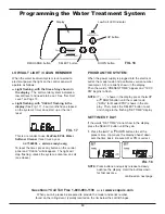
Страница 12: ...nnected to electrical power the light on the control panel will operate as follows Light flashing with the time of day shown in the display The salt monitor system indicates a low salt level and needs to be set See Set Salt Level on Page 13 Light flashing with CLEAn flashing in the display See Fig 17 Four months have elapsed on the system s timer since start up or the last reset This is a reminder...

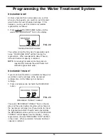
Страница 13: ...ton once again to display a flashing 2 00AM and the words SET RECHARGE TIME This is a good time for the recharge to start in most households because water is not in use FIG 20 SET SALT LEVEL The water treatment system has a low salt indicator light to remind you to refill the storage tank with salt NOTE You must set salt level each time salt is added to the water softener To set this monitor syste...

Страница 14: ...r heater will refill with bypass hard water RECHARGE TONIGHT If you do not want to start an immediate recharge but would like an extra recharge at the next preset recharge time do the following to schedule a recharge 1 Press and release do not hold the RECHARGE button The words RECHARGE TONIGHT flash in the dis play and the water treatment system will recharge at the next preset recharge time If y...

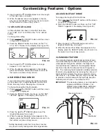
Страница 15: ...ver you can adjust this time from 1 to 15 minutes in length To change this cycle time 1 Press and hold the SELECT button until the screen in Figure 27 is displayed 2 Press the SELECT button three times to display the Set Clean Time screen See Figure 29 2 Press the SELECT button twice again so that SET CLEAN OFF or SET CLEAN ON flashes in the display See Figure 28 15 SET SALT EFFICIENCY When this f...

Страница 16: ...efault setting To change this setting 1 Press and hold the SELECT button until the screen in Figure 24 is displayed 2 Press the SELECT button four times so that 12 hr or 24 hr flashes in the display See Figure 30 FIG 30 FIG 32 Top Distributor Cleansing Screen Resin Tank FIG 33 ADJUSTABLE FAST RINSE To change the length of the Fast Rinse 1 Press and hold the SELECT button until the screen in Figure...

Страница 17: ... age level lower and to refill more often to avoid salt bridging Recommended Salt Nugget pellet or coarse solar salts with less than 1 impurities Salt Not Recommended Rock salt high in impurities block granulated table ice melting ice cream making salts etc BREAKING A SALT BRIDGE Sometimes a hard crust or salt bridge forms in the brine tank It is usually caused by high humidity or the wrong kind o...

Страница 18: ...ce water level in the tank This will also assure that the system is completely recharged and ready to provide softened water again Check the water level in the tank by look ing down the brinewell If the water level does not drop after a recharge the problem has not been resolved Call 1 800 693 1138 PROTECT THE WATER TREATMENT SYS TEM FROM FREEZING If the water treatment system is installed where i...

Страница 19: ...m Contact a licensed plumber 6 Brine float dirty or broken Clean or replace Brine Valve Float Assembly 7 Leak between valve and resin tank Replace o rings between resin tank and valve Water hard some times 1 Incorrect time set Check and change time setting 2 Incorrect water hardness set Refer to Set Water Hardness section to set correctly 3 Incorrect model code programmed Refer to Program the Wate...

Страница 20: ...e water is in contact with the salt and not separated by a salt bridge See Breaking A Salt Bridge section 5 While in this diagnostic screen the following infor mation is available and may be beneficial for vari ous reasons This information is retained by the computer from the first time electrical power is applied to the electronic controller a Press the p UP button to display the number of days t...

Страница 21: ...b ing or brine valve riser pipe 2 After observing fill press the RECHARGE button to move the system s valve into the brine position A slow flow of water to the drain will begin Verify brine draw from the brine tank by shining a flash light into the brinewell and observing a noticeable drop in the liquid level This may take 15 to 20 minutes NOTE Be sure water is in contact with the salt and not sep...

Страница 22: ...22 Water Treatment System Exploded View 8 7 6 5 26 28 15 16 18 19 20 11 22 23 24 25 8 6 3 9 10 7 5 2 1 21 14 13 17 27 12 Valve Assembly See Pages 24 25 for parts 70 71 72 4 ...

Страница 23: ...Decal 16 7331834 Repl Electronic Control Board PWA 17 7351054 Power Supply 24V DC 18 7155115 Cover Brinewell 19 7338145 Brinewell 7332204 Brinewell Mounting Hardware Kit includes Key Nos 20 22 20 á Wing Nut 1 4 20 21 á Spacer 19 1 mm long 22 á Screw 1 4 20 x 15 9 mm 7331258 Overflow Hose Adaptor Kit includes Key Nos 23 25 23 á Adaptor Elbow 24 á Grommet 25 á Hose Clamp 26 7310202 Brine Valve Assem...

Страница 24: ...24 Valve Exploded View 51 50 52 53 55 56 59 58 57 60 61 66 67 62 63 64 68 69 70 71 75 65 76 77 79 78 80 81 82 Wear Strip Seal Cross section View 83 84 85 86 87 88 89 90 54 72 73 74 ...

Страница 25: ... Turbine Support Assembly including 2 O Rings See Key No 72 1 ea of Key Nos 73 74 73 á Turbine Support Shaft 74 á Turbine 75 7082053 Valve Body 76 7081201 Retainer Nozzle Venturi 77 7342649 O Ring 6 4 x 9 5 mm pack of 2 78 1202600 Nut Ferrule 7257454 Nozzle Venturi Assembly includes Key Nos 76 77 79 87 79 7081104 Housing Nozzle Venturi 80 7095030 Cone Screen 81 1148800 Flow Plug 1 1 lpm 82 7114533...

Страница 26: ... unusual force of nature such as but not limited to flood hurri cane tornado or earthquake Warrantor is excused if failure to perform its warranty obligations is the result of strikes government regulation materials shortages or other circumstances beyond its control THERE ARE NO WARRANTIES ON THE WATER TREATMENT SYSTEM BEYOND THOSE SPECIFICALLY DESCRIBED ABOVE ALL IMPLIED WARRANTIES INCLUDING ANY...

Отзывы: