71
C
ONNECTIONS OF THE MODEL WITH SEPARATE BYPASS
The very first connection to be carried out is that of the protection conductor (earth cable), which must
be connected to the terminal marked PE. The UPS must not operate without being connected to an
earthing system
THE INPUT AND THE BYPASS NEUTRALS MUST ALWAYS BE CONNECTED.
THE INPUT AND BYPASS LINES MUST REFER TO THE SAME NEUTRAL POTENTIAL.
DO NOT CONNECT THE OUTPUT NEUTRAL TO THE INPUT OR BYPASS NEUTRAL.
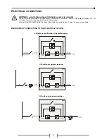
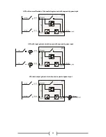
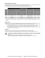
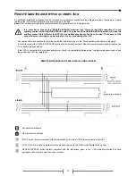
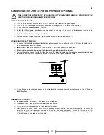
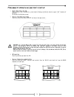
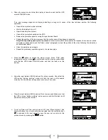
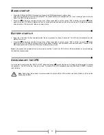
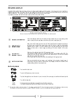
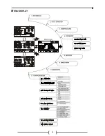
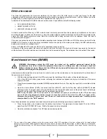
Connect the input and output cables to the terminal board as shown in the figure below:
Note 1
: The protection conductor (earth cable) connection must be carried out through eyelet terminal stud M6
Note 2:
Connections to the BATTERY module are required only when the optional Battery Box is present
R.E.P.O.
This isolated input is used to turn off the UPS remotely in case of emergency.
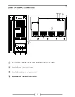
This UPS is provided from the factory with “Remote Emergency Power Off” (R.E.P.O.) terminals short-circuited (
see "Views of
the UPS connections"
). If it is to be installed, remove the short-circuit and connect to the normally closed contact of the
stopping device by using a cable that ensures a double isolation connection.
In case of emergency, the R.E.P.O.control is opened by activating the stopping device; the UPS enters stand-by mode (see
"USE" section) and powers off the load completely.
The R.E.P.O circuit is self-powered with SELV type circuits. Therefore, no external power supply voltage is required. When
closed (normal condition) a maximum current is present.
E
XTERNAL
S
YNC
This non-isolated input can be used to synchronise the inverter output with an opportune signal coming from an external source.
If it is to be installed it is necessary to:
¾
Use an isolation transformer with an isolated single-phase output (SELV) within the range 12÷24Vac with a power
≥
0.5VA
¾
Connect the transformer secondary to the "EXTERNAL SYNC" terminal (see
"Views of the UPS connections”)
using a
double isolation cable with a 1mm2 cross section. Warning: always respect the polarisation as in the figure below:
Once the installation has been completed, the command has to be enabled by using the advanced configuration software UPS
Tools in the CD-ROM provided with the UPS.

