90
Project 2: Adjust LED Brightness
(1)
Description
:
In previous lesson, we control LED on and off and make it blink.
In this project, we will control LED brightness through PWM to simulate
breathing effect. Similarly, you can change the step length and delay time
in the code so as to demonstrate different breathing effect.
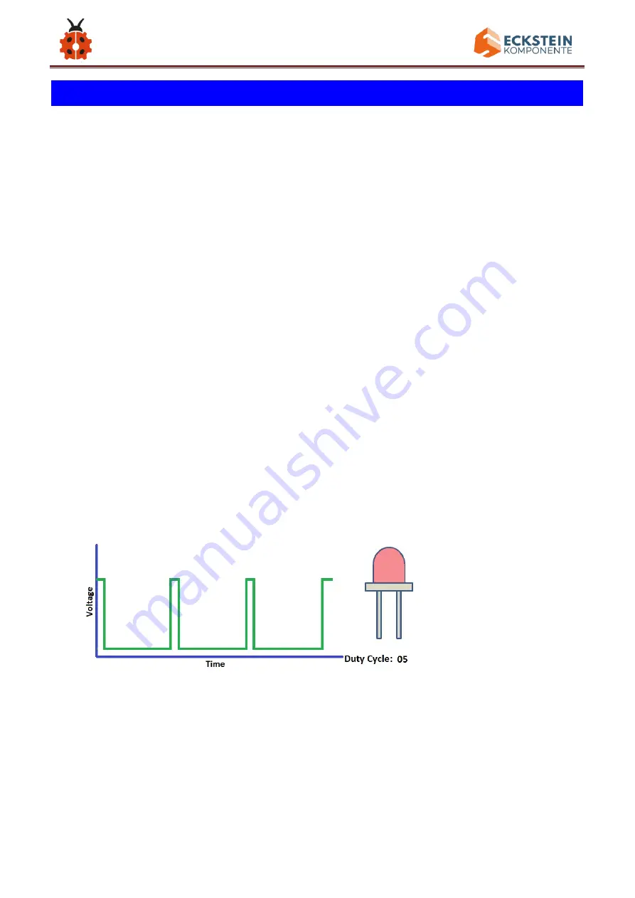
PWM is a means of controlling the analog output via digital means. Digital
control is used to generate square waves with different duty cycles (a signal
that constantly switches between high and low levels) to control the analog
output.In general, the input voltage of port are 0V and 5V. What if the 3V is
required? Or what if switch among 1V, 3V and 3.5V? We can
’
t change
resistor constantly. For this situation, we need to control by PWM.
For the Arduino digital port voltage output, there are only LOW and HIGH,
which correspond to the voltage output of 0V and 5V. You can define LOW
Содержание KS0530
Страница 15: ...15 Click JUST DOWNLOAD ...
Страница 24: ...24 Copy driver folder to D drive Right click Computer Properties Device Manager You will view Unknown Device ...
Страница 25: ...25 Click Unknown devices to select Update Device Management Click Browse manually ...
Страница 26: ...26 Find the drivers file and tap Next ...
Страница 27: ...27 Click install this driver software anyway Then click Close and check the serial port ...
Страница 31: ...31 The functions of all symbols are demonstrated below ...
Страница 34: ...34 delay 1000 delay 1 second Then let s make monitor show Hello World Open Arduino IDE and select Arduino UNO ...
Страница 38: ...38 Installation Diagram Prototype Part 2 ...
Страница 39: ...39 Components Needed Installation Diagram ...
Страница 40: ...40 Prototype Part 3 ...
Страница 41: ...41 Components Needed Installation Diagram ...
Страница 42: ...42 Prototype Part 4 Components Needed ...
Страница 43: ...43 Installation Diagram Prototype ...
Страница 44: ...44 Part 5 Components Needed Installation Diagram mind the installation direction ...
Страница 45: ...45 Prototype Part 6 Components Needed ...
Страница 46: ...46 Installation Diagram Prototype Part 7 ...
Страница 47: ...47 Components Needed ...
Страница 48: ...48 Installation Diagram mind the installation direction Prototype Part 8 ...
Страница 49: ...49 Components Needed Installation Diagram ...
Страница 50: ...50 Prototype Part 9 Components Needed ...
Страница 51: ...51 Installation Diagram mind the installation direction of the servo Prototype Part 10 ...
Страница 52: ...52 Components Needed Installation Diagram ...
Страница 55: ...55 Installation Diagram pay attention to the angle of the servo as shown in the picture Prototype Part 12 ...
Страница 56: ...56 Components Needed Installation Diagram ...
Страница 57: ...57 Prototype Part 13 Components Needed ...
Страница 58: ...58 Installation Diagram Prototype Part 14 adjust the angle of the servo before starting this step ...
Страница 60: ...60 void loop Installation Diagram ...
Страница 61: ...61 Prototype Part 15 Components Needed ...
Страница 62: ...62 Installation Diagram Prototype Part 16 ...
Страница 63: ...63 Components Needed Installation Diagram ...
Страница 64: ...64 Prototype Part 17 Components Needed ...
Страница 65: ...65 Installation Diagram Prototype Part 18 ...
Страница 66: ...66 Components Needed Installation Diagram ...
Страница 67: ...67 Prototype Part 19 Components Needed ...
Страница 68: ...68 Installation Diagram ...
Страница 69: ...69 Prototype Start Wiring ...
Страница 71: ...71 Connect the servo downward to D9 on the main board ...
Страница 72: ...72 Connect the servo upward to D10 on the main board ...
Страница 73: ...73 Connect the solar panel to the SOLAR end ...
Страница 74: ...74 Connect the LCD module to A4 and A5 blue line to A4 and green line to A5 ...
Страница 75: ...75 Connect the push button module to D2 ...
Страница 76: ...76 Connect the passive buzzer to D6 ...
Страница 77: ...77 Connect the temperature and humidity sensor to D7 ...
Страница 78: ...78 Connect the digital light intensity module to the main board blue line to SDA and green line to SCL ...
Страница 79: ...79 Keep the LED display in front of you as reference the photoresistor on the left is connected to A0 ...
Страница 80: ...80 Keep the LED display in front of you as reference the photoresistor on the right is connected to A1 ...
Страница 81: ...81 Keep the LED display in front of you as reference the photoresistor on the back is connected to A2 ...
Страница 82: ...82 Keep the LED display in front of you as reference the photoresistor ahead is connected to A3 ...
Страница 83: ...83 Wire up the power module to power the main board G to GND and V to VIN ...
Страница 92: ...92 3 Connection Diagram 4 Test Code keyestudio sun_follower lesson 2 1 PWM http www keyestudio com ...


