background image


MN300820 Rev B4 

19   

|


Configuration Using WebCal

®

 Step 

Three 


EchoTouch

®

 can be configured before installation.  The transmitter features non-volatile memory, so any 

setting configured before installation will not be lost when the switch is powered down.  To configure, follow the 
steps below: 

1. Install 

WebCal

®

 software 

a. Go 

to 

www.flowline.com/webCal-software/

 and select language version. 

b.  Review how USB

®

 Fob interfaces with EchoTouch

®

 and your computer. 

2.  Measure the Tank 

a.  Begin by measuring the key tank and fitting dimensions.   
b.  Correct tank dimensions will result in accurate sensor measurement. 

3. Sensor 

Configuration 

a.  Configures Loop Fail-Safe, Output at Empty & Startup Condition for the sensor. 

4. Dimensional 

Entry 

a.  Distance Mode (default) 

i.  Basic information for operation (Sensor Height & Fill-Height). 

5. Tank 

Level 

Confirmation 

a.  Confirm the values are accurate for the application. 

6.  Write to Unit 

a.  Uploads configuration into the sensor. 
b.  Access to a customer wiring diagram specific to the relay configuration. 

Note: 

When configuring EchoTouch

®

, choose either the WebCal

®

 or Push Button method.  Push 

Button is only available with the US06 and US12 series.  Either method will accomplish the goal 
of sensor configuration.  Changes to the configuration can be made using the alternative method.  
When beginning with one method, it is recommended to complete the configuration before using 
the other method to make any adjustments.


Содержание FLOWLINE US01 Series

Страница 1: ...Flowline Inc 10500 Humbolt Street Los Alamitos CA 90720 p 562 598 3015 f 562 431 8507 w flowline com MN300820 Rev B4 US01 US03 US06 US12 Series Manual Echotouch Ultrasonic Level Transmitter ...

Страница 2: ...5 Intrinsically Safe Control Drawings 7 Safety Precautions 9 Getting Started 11 Setup Overview 11 Components 12 WebCal vs Display Configuration 14 Understanding Sensor Height Height 15 Understanding Fill Height Fill H 16 Sensor Output to Local Display 18 Configuration Using WebCal 19 Step 1 Install WebCal Software 20 USB Fob Interface 21 Step 2 Measure the Tank 22 Step 3 Sensor Configuration 23 St...

Страница 3: ... Common Wiring to Displays Controllers PLCs 46 WebCal Appendix 49 Sensor Configuration 49 Volumetric Configuration 51 Tank Level Confirmation 54 Write to Unit 55 Display Appendix 56 Air Gap vs Liquid Level 56 How to reverse the current output Rev mA 57 How to Setup to Start up Power 58 Values Menu 59 SETUP 59 Diagnostic DIAG parameters 59 Reset 60 Factory Settings 61 User Settings 61 Troubleshooti...

Страница 4: ...yvinylidene Fluoride PVDF Cable jacket mat l Polyvinyl Chloride PVC Cable type 4 conductor with shield Cable length 4 121 9 cm Cable Min Temp 200 C Process Mount 2 NPT or 2 G Gasket Viton A G thread only Classification Intrinsically Safe Compliance CE RoHS Electrical Supply Voltage 14 28 Vdc Signal 4 to 20 mA current loop 22 mA max Signal invert 4 20mA or 20 4mA Signal fail safe 4mA 20mA 21mA 22mA...

Страница 5: ...MN300820 Rev B4 5 Introduction continued Step One DIMENSIONS Dimensions for US01 US03 Series Dimensions for US06 Series ...

Страница 6: ...0 and substantially reducing their measurement reliability At the core of Reflective Technology is a simple fact Unlike flat horizontal surfaces significant water droplets cannot adhere to smooth vertical surfaces By orienting the transducer vertically condensation runs off the transducer and does not affect sensor performance The unimpeded transmit and receive signals are redirected to and from t...

Страница 7: ...afe Entity Parameters Ui Vmax 28 VDC Ii Imax 100 mA Pi 840 mW Li 2 46 mH Ci 0 μF CSA for U S Class I Div 1 Groups A B C and D T4 Class II Div 1 Groups E F G T4 Class III T135 C Class I Zone 0 IIC AEx ia T4 Ga Class II Zone 20 IIIC AEx ia T135 C Da CSA for Canada Class I Division 1 Groups A B C and D T4 Class II Division 1 Groups E F G T4 Class III T135 C Ex ia IIC T4 Ga Ex ia IIIC T135 C Da IECEx ...

Страница 8: ...Safe Entity Parameters Ui Vmax 28 VDC Ii Imax 100 mA Pi 840 mW Li 2 46 mH Ci 0 μF CSA for U S Class I Div 1 Groups A B C and D T4 Class II Div 1 Groups E F G T4 Class III T135 C Class I Zone 0 IIC AEx ia T4 Ga Class II Zone 20 IIIC AEx ia T135 C Da CSA for Canada Class I Division 1 Groups A B C and D T4 Class II Division 1 Groups E F G T4 Class III T135 C Ex ia IIC T4 Ga Ex ia IIIC T135 C Da IECEx...

Страница 9: ...d resistant the EchoTouch is not designed to be operational when immersed It should be mounted in such a way that the enclosure and transducer do not come into contact with the application media under normal operational conditions Warning Potential Electrostatic Charging Hazard Handling Static Sensitive Circuits Devices When handling the transmitter the technician should follow these guidelines to...

Страница 10: ... est immergé Il doit être monté de telle sorte que l enceinte et le transducteur ne soient pas en contact avec le support d application dans des conditions normales de fonctionnement Avertissement Danger potentiel de charge électrostatique manipulation de circuits dispositifs sensibles à l électricité statique lors de la manipulation de l émetteur le technicien doit suivre ces directives pour rédu...

Страница 11: ... on using the WebCal configuration software 4 Configure Sensor with Push Button Section Four a Section 4 contains information on using the Push Button Display to configure the sensor b Only applies to the US06 US12 Series 5 Install the sensor Section Five a Section 5 contains information about the sensor location placement and its mechanical installation 6 Wire the sensor Section Six a Section 6 c...

Страница 12: ...US12 0011 01 Included US06 0001 00 19 7 6m 8 20cm 2 NPT Not Included US06 0001 01 Included US06 0011 00 2 G Not Included US06 0011 01 Included US03 0001 00 9 8 3m 4 10cm 2 NPT Not Included TYPE 6P 4 Pigtail WebCal only US03 0001 01 Included US03 0011 00 2 G Not Included US03 0011 01 Included US01 0001 00 4 9 1 5m 1 5 3 81cm 2 NPT Not Included US01 0001 01 Included US01 0011 00 2 G Not Included US0...

Страница 13: ...us US06 0001 00 19 7 6m 8 20cm 2 NPT Not Inclus US06 0001 01 Inclus US06 0011 00 2 G Not Inclus US06 0011 01 Inclus US03 0001 00 9 8 3m 8 20cm 2 NPT Not Inclus TYPE 6P 4 Natte WebCal seulement US03 0001 01 Inclus US03 0011 00 2 G Not Inclus US03 0011 01 Inclus US01 0001 00 4 9 1 5m 4 10cm 2 NPT Not Inclus US01 0001 01 Inclus US01 0011 00 2 G Not Inclus US01 0011 01 Inclus Viton Gasket version file...

Страница 14: ...h can be configured before installation or after installation The transmitter features non volatile memory so any settings configured before installation will not be lost when the sensor is powered down To start the following information is required Basic Tank Information o HEIGHT Sensor Height Distance from the bottom of the tank to the bottom of the sensor o FILL H Fill Height Distance from the ...

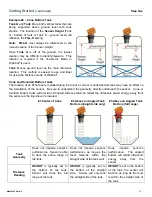
Страница 15: ...e of the tank and any risers fittings structures or extensions associated with the tank or the installation see examples below The reference point for definition of the Sensor Height is always the bottom of the mounting nut Simple Vertical Tank Dome Top Raises HEIGHT Sensor Off center Changes HEIGHT Simple Open Top Tank Sensor Extends into Sump Cone Bottom Elevates HEIGHT Simple Horizontal Tank Ri...

Страница 16: ...the top of the tank Note The ratio of height to diameter of the riser must be no greater than 2 1 Any higher and the sensor will target the inside wall of the riser Example 2 Dome Top Tanks Tank C has a tall enough dome whereas the Dead Band is above the straight side of the tank The FILL H can be set to the top of the straight side this is advantageous because the top of the straight side is typi...

Страница 17: ...allation of the sensor Be sure to understand the geometry directly underneath the sensor Cone or rounded bottom tanks will provide off angled surfaces that can reflect the ultrasonic sound energy away from the sensor as the liquid level is lowered 1 Center of Cone 2 Above an Angled Tank Bottom straight side only 3 Above an Angled Tank Bottom full range Tank Geometry Does not impede sensor s perfor...

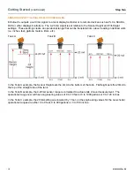
Страница 18: ...ed units i e inches feet gallons meters liters etc Tank A Tank B Tank C In the Tank A example the Sensor Height sets the 4mA to the bottom of the tank Fill Height sets the 20mA to the top of the straight side of the tank In the Tank B example the 4 20mA sensor range is correlated to actual units of level measurement The operational range now will have engineering values of 0 to 10 feet or 0 to 100...

Страница 19: ...uration a Configures Loop Fail Safe Output at Empty Startup Condition for the sensor 4 Dimensional Entry a Distance Mode default i Basic information for operation Sensor Height Fill Height 5 Tank Level Confirmation a Confirm the values are accurate for the application 6 Write to Unit a Uploads configuration into the sensor b Access to a customer wiring diagram specific to the relay configuration N...

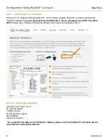
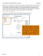
Страница 20: ...must download and install WebCal prior to plugging in the USB Fob LI99 2001 Please go to flowline com webcal software and select your language version WEBCAL SYSTEM REQUIREMENTS Windows XP Vista 7 8 10 32 or 64 bit system 1 USB 2 0 port 10 mB hard drive space 256 mB RAM Internet connection For complete information on the WebCal software please refer to the WebCal manual located at www flowline com...

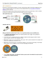
Страница 21: ...e wires The maximum cable distance between the computer and EchoTouch is 15 This only applies for configuring the EchoTouch Once EchoTouch is configured and prior to installation isolate the white and green wires from active power to prevent a short from the configuration circuit Note When using the Fob do not add VDC or VAC power The Fob when connected to the computer will provide the required po...

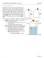
Страница 22: ...her hand sensors installed in risers nozzles will result in a higher HEIGHT value The basic measurements Height and Fill H for configuration are described below 1 HEIGHT Sensor Height Distance from the bottom of the tank to the Bottom of Sensor a The bottom of the tank will be the sensor s zero level empty level b This setting determines the 4mA location 2 FILL H Fill Height Distance from the bott...

Страница 23: ...ineer at 562 598 3015 Note For complete information on the WebCal software please refer to the WebCal manual located at flowline com webcal software STEP 3 SENSOR CONFIGURATION Configures the Loop Fail Safe Output at Empty and Startup Condition for the sensor Note When configuring EchoTouch choose either the WebCal or Push Button method Either method will accomplish the goal of sensor configuratio...

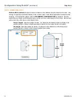
Страница 24: ...puts refer to VOLUMETRIC CONFIGURATION on page 40 The two values Sensor Height and Fill Height below set the 4 20 mA current span for the sensor Both values will be set in the units shown under Height Units Sensor Height Sets the location for 4mA It is based on the distance from the Empty level position bottom of tank to the Measurement location for the sensor bottom of sensor Fill Height Sets the...

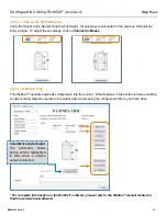
Страница 25: ...TEP 6 WRITE TO UNIT This WebCal operation uploads configuration into the sensor Other features in the section include providing a custom wiring diagram specific to the signal output and saving the configuration file to your hard drive For complete information on the WebCal software please refer to the WebCal manual located at flowline com webcal software Volumetric Sensor Output The Volumetric Mod...

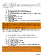
Страница 26: ...06 US12 series EchoTouch peut être configuré avant l installation L émetteur dispose d une mémoire non volatile de sorte que tout réglage configuré avant l installation ne sera pas perdu lorsque le commutateur est mis hors tension Pour configurer procédez comme suit Pages 32 à 36 1 Mesurer le réservoir a Commencez par mesurer le réservoir de clés et les dimensions de montage b Les dimensions corre...

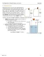
Страница 27: ... hand sensors installed in risers nozzles will result in a higher HEIGHT value The basic measurements Height and Fill H for configuration are described below 1 HEIGHT Sensor Height Distance from the bottom of the tank to the Bottom of Sensor a The bottom of the tank will be the sensor s zero level empty level a This setting determines the 4mA location 2 FILL H Fill Height Distance from the bottom ...

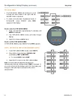
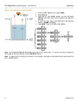
Страница 28: ...P LEVEL MENU items will rotate through display 3 Use OK to choose a MENU item How to exit the TOP LEVEL MENU In TOP LEVEL MENU press SELECT when RUN appears STEP 2 SETTING THE UNITS OF MEASUREMENT UNITS 1 In the TOP LEVEL MENU mode select UNITS 2 Press OK to choose between INCHES CM centimeter FEET or METERS a To cancel UNITS Select EXIT 3 Select EXIT to return to the TOP LEVEL MENU Note EchoTouch...

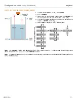
Страница 29: ... to the bottom of the tank 4 To enter the value press and hold OK for 2 seconds and release SAVED will display 5 Select EXIT to return to TOP LEVEL MENU Note The HEIGHT setting also determines the 4 mA current location To reverse the current output with 20mA at the bottom of the tank use the REV MA function Note To speed up the scrolling of the values on the display hold down the OK button while h...

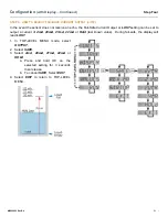
Страница 30: ...iquid to the bottom of the tank 4 To enter the value press and hold OK for 2 seconds and release SAVED will display 5 Select EXIT to return to TOP LEVEL MENU Note The Fill Height FILL H setting determines the 20 mA current span To reverse the current output with 4mA being at the top of the tank use the REV MA function Note To speed up the scrolling of the values on the display hold down the OK but...

Страница 31: ...urrent Output or LOST setting can be set to output a current of 4mA 20mA 21mA 22mA or Hold last known value During fail safe the display will read LOST 1 In TOP LEVEL MENU mode select OUTPUT 2 Select SAFE 3 Select 4mA 20mA 21mA 22mA or HOLD a Press and hold OK on the selected setting for 3 seconds then release b To cancel SAFE Select EXIT 4 Select EXIT to return to TOP LEVEL MENU ...

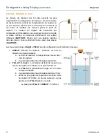
Страница 32: ...utre part les capteurs installés dans les risers buses entraîneront une valeur plus élevée HAUTEUR Les mesures de base Height et Fill H pour la configuration sont décrites ci dessous 1 HEIGHT Hauteur du capteur Distance du fond du réservoir au bas du capteur a Le fond du réservoir correspondra au niveau zéro vide du capteur b Ce paramètre détermine l emplacement 4mA 2 FILL H Fill Height La distanc...

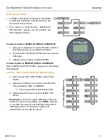
Страница 33: ...ournent à travers l affichage 3 Utilisez OK pour choisir un élément MENU Comment quitter le MENU DE NIVEAU SUPÉRIEUR Dans le MENU HAUT DE NIVEAU appuyez sur OK lorsque RUN apparaît ÉTAPE 2 RÉGLAGE DES UNITÉS DE MESURE UNITS 1 Dans le mode TOP LEVEL MENU sélectionnez UNITS 2 Appuyez sur SELECT pour choisir entre INCHES CM centimètre FEET ou METERS a Pour annuler UNITS sélectionnez EXIT 3 Sélectionn...

Страница 34: ...ir 4 Pour entrer la valeur appuyez et maintenez la touche OK pendant 2 secondes et relâchez SAVED s affichera 5 Sélectionnez EXIT pour revenir au MENU TOP LEVEL Remarque Le paramètre HEIGHT détermine également l emplacement actuel de 4 mA Pour inverser la sortie de courant avec 20 mA au bas du réservoir utilisez la fonction REV MA Remarque Pour accélérer le défilement des valeurs sur l affichage m...

Страница 35: ...ervoir 4 Pour entrer la valeur appuyez et maintenez la touche OK pendant 2 secondes et relâchez SAVED s affichera 5 Sélectionnez EXIT pour revenir au MENU TOP LEVEL Remarque Le paramètre de hauteur de remplissage FILL H détermine la portée de courant de 20 mA Pour inverser la sortie de courant avec 4mA en haut du réservoir utilisez la fonction REV MA Remarque Pour accélérer le défilement des valeu...

Страница 36: ...ut être configuré pour afficher un courant de 4mA 20mA 21mA 22mA ou Hold dernière valeur connue En cas de panne de sécurité l affichage se lire LOST 1 En mode TOP LEVEL MENU sélectionnez OUTPUT 2 Sélectionnez SAFE 3 Sélectionnez 4mA 20mA 21mA 22mA ou HOLD a Appuyez et maintenez OK sur le réglage sélectionné pendant 3 secondes puis relâchez b Pour annuler SAFE sélectionnez EXIT 4 Sélectionnez EXIT ...

Страница 37: ...m a standing position sliding across the seat or walking a distance 2 Avoid touching electrical terminals of the part unless making connections 3 DO NOT open the unit cover until it is time to calibrate MOUNTING GUIDE 1 Do not mount at an angle 2 Liquid should never enter the dead band 3 Side Wall a Mount at least 3 from the side wall 4 Do not mount where obstacles will intrude on sensor s beam wi...

Страница 38: ...e pas monter où les obstacles s immisceront sur la largeur du faisceau du capteur a monter au moins 3 de la paroi latérale 5 Ne pas monter sous vide 6 Ne pas monter au centre d un réservoir en forme de dôme 7 Dans le réservoir inférieur cône positionnez le capteur sur la partie la plus profonde du réservoir Installation dans les raccords existants si le raccord existant est plus grand que les fils...

Страница 39: ...52 2890 Tank Adapter w 3 x2 Reducer Bushing LM52 3890 w LM52 2800 3 Tank Adapter Socket x Thread LM52 3890 Tank Adapter Thread x Thread Do not use thread x thread 2 Riser Installations with tall narrow risers can impede the acoustic signal a Core Out Concrete Applications where a tank with a concrete ceiling that has been cored out can also be considered as a riser type application In these applic...

Страница 40: ...cer bushing to complete the installation 2 Flange w LM52 2850 3 Flange w Reducer Bushing LM52 3800 3 Flange LM52 3850 4 Side Mount Bracket For installations in open tanks and sumps use the LM50 1001 series side mount bracket LM50 1001 Shown Note The Side Mount Bracket LM50 series is not designed for use with stand pipes or as a method to secure stand pipes There are too few threads to properly hol...

Страница 41: ...f the pipe should remain submerged at all times to prevent foam from entering the pipe e Cut a 45 notch at the bottom of the pipe Drill a 1 4 pressure equalization hole in the dead band f The pumps should not drive liquid past the open end of the stand pipe which causes the liquid in the pipe to oscillate Note Never allow the bottom of the stand pipe to become exposed to air This will break the li...

Страница 42: ... loop powered 4 20 mA control circuit The typical way to use this feature is to connect a positive supply to the input and to sense the current flow out of the output The cabling should be a shielded twisted pair to minimize EMI interference Typically 20 to 24 gauge wire is used in this application ...

Страница 43: ...mA alimenté en boucle Le moyen typique d utiliser cette fonction est de connecter une alimentation positive à l entrée et de détecter le flux de courant sortant de la sortie Le câblage doit être une paire torsadée blindée pour minimiser les interférences EMI Typiquement le fil de calibre 20 à 24 est utilisé dans cette application ...

Страница 44: ...r significant property damage can occur due to a spill the installation must have a redundant backup safety system Wiring should always be completed by a licensed electrician Supply voltage should never exceed 28 VDC Use 16 to 24 AWG for connecting to terminals Protect the sensor from excessive electrical spikes by isolating the power whenever possible The sensor materials must be chemically compa...

Страница 45: ...nelle ou des dégats matériels importants peuvent survenir en raison d un déversement l installation doit comporter un système de sécurité de secours redondant Le câblage doit toujours être complété par un électricien autorisé La tension d alimentation ne doit jamais dépasser 28 VDC Protégez le capteur contre les pointes électriques excessives en isolant l alimentation chaque fois que cela est poss...

Страница 46: ...he EchoTouch to common display controllers and PLC s DataView LI55 Series Level Controller DataLoop LI23 Series Level Indicator without the backlight DataLoop LI23 Series Level Indicator with the backlight Note Always refer to control drawing 600820 for the US06 US12 series and control drawing 610125 for US01 and US03 series ...

Страница 47: ...ng the EchoTouch to common display controllers and PLC s Commander LI90 Series Multi Tank Level Controller DataPoint LC52 Series Level Controller JWA mode Factory Setting Generic Loop Powered Display Note Always refer to control drawing 600820 for the US06 US12 series and control drawing 610125 for US01 and US03 series ...

Страница 48: ...IRING TO DISPLAY CONTROLLERS PLC S Below is a quick review of wiring the EchoTouch to common display controllers and PLC s Generic PLC Note Always refer to control drawing 600820 for the US06 US12 series and control drawing 610125 for US01 and US03 series ...

Страница 49: ... during a fail safe condition Full The output will revert to the current value for a full condition When 4 mA at Bottom is selected the sensor will output 20 mA during a fail safe condition If 20 mA at Bottom is selected the sensor will output 4 mA during a fail safe condition Overfill 21mA The sensor will output 21mA during a fail safe condition Overfill 22mA The sensor will output 22mA during a ...

Страница 50: ... output will revert to the selected current value for an empty condition o 4 mA at Bottom The sensor will output 4 mA while the sensor powers up o 20 mA at Bottom The sensor will output 20 mA while the sensor powers up Mid Tank 12 mA The sensor will output 12 mA while the sensor powers up Full The output will revert to the selected current value for a full condition o 4 mA at Bottom The sensor wil...

Страница 51: ... the height of the tank This means that the current output will track the volume of the tank in gallons or liters Depending on the shape of the tank the values may be a linear or non linear scale In the same examples below the sensors are also configured with SH 64 and FH 60 The current output in a linear tank will act as expected with volume increase matching equal changes to level However the cu...

Страница 52: ...nits as Distance or Volume After choosing the Sensor Output Units select the units of measurement in the pull down to the left Units of Measurement Distance Volume Inches Cm Feet Meters Gallons Liters Distance Sensor Output Units Vertical Cylinder Example Enter the dimensions of the tank You must enter data in all fields shown Sensor Height Distance from the bottom of the tank to the bottom of the...

Страница 53: ...e tank to the top of the straight side wall Diameter Distance of the inside tank diameter Volume Tank Capacity Vertical Cylinder Example After entering the dimensions press the Capacity button to show the Calculated Capacity of the tank If the Calculated Capacity is slightly different than the expected capacity click on the Adjust Capacity box and enter the expected capacity of the tank If the Adj...

Страница 54: ...nk to the bottom of the sensor Fill Height Distance from the bottom of the tank to the operational full level of liquid 20mA This setting defines the location of full current output and is the top of the sensor s measurement range Capacity The total volume of the tank Only shown when gallons or liters are selected Note By extending the empty 4mA to the bottom of the tank the 4 20 mA output will tr...

Страница 55: ...e setting designed to help solve performance or operational issues for specific applications Changing these setting will alter the factory default performance or operation of your sensor Increase Output Filtering Placing a check mark in the box will increase the filtering averaging of the analog output Use this filter if the 4 to 20 mA output requires a smoother output for the application such as ...

Страница 56: ... the tank LIQUID mode or the amount of air in the tank AIR mode This function does not influence the current output just the display on the sensor 1 In TOP LEVEL MENU mode select DISPLAY 2 Select LIQUID or AIR a Press and hold OK on the selected setting for 3 seconds then release b To cancel DISPLAY Select EXIT 3 Select EXIT to return to TOP LEVEL MENU Liquid Mode Air Mode ...

Страница 57: ...t top then use the REV MA setting to reverse the current output With REV MA set to NORM factory default 4mA will be at the bottom and 20 mA at the top of the tank With REV MA set to REV 20mA will be at the bottom and 4mA at the top of the tank 1 In TOP LEVEL MENU mode select OUTPUT 2 Select REV MA 3 Select 4 BOTT or 4 TOP a Press and hold OK on the selected setting for 3 seconds then release a To ...

Страница 58: ...cquires the level reading the output current can be preset in order to avoid any false alarms during this window The options for start up are 4mA 12mA 20mA or 22mA 1 In TOP LEVEL MENU mode select OUTPUT 2 Select STRTUP 3 Select 4mA 12mA 20mA or 22mA a Press and hold OK on the selected setting for 3 seconds then release a To cancel STRTUP Select EXIT 4 Select EXIT to return to TOP LEVEL MENU ...

Страница 59: ...ill list the following information a UNITS b DISPLY c REV MA d SAFE e HEIGHT f FILL H g START UP 4 Select EXIT to return to TOP LEVEL MENU DIAGNOSTIC DIAG PARAMETERS This mode runs diagnostic tests that confirm operation of EchoTouch This is a production test feature used by the factory to confirm operation 1 In TOP LEVEL MENU select VALUES 2 Select DIAG 3 DIAG will list the following settings a D...

Страница 60: ... Eight RESET EchoTouch enables the end user to reset the entire configuration back to the original factory settings 2 In TOP LEVEL MENU mode select VALUES 3 Select RESET 4 Select YES a To cancel the reset Select NO 5 Select EXIT to return to TOP LEVEL MENU ...

Страница 61: ...op Start up 4mA 12mA 20mA 22mA TROUBLESHOOTING PROBLEM SOLUTION No Unit Detected in WebCal If WebCal cannot detect EchoTouch when connected to the computer Check that the LI99 2001 Fob is connected to the USB port Check that all four wires Red Black White and Green are securely attached to the Fob Check Device Manager and confirm that both drivers WebCal Configuration EchoFob are present If the ab...

Страница 62: ...mitter indicates a current of 0 mA Check the wiring for an open circuit An open circuit is the most common issue with a 0 mA signal Transmitter jumps to a current reading between 19 and 20 mA Check the installation of the transmitter Bad installation fittings will cause false signals near the top of the tank which typically translates to a signal between 19 and 20 mA Also look for interference jus...

Страница 63: ...MN300820 Rev B4 63 Display Appendix continued Section Eight ...

Страница 64: ...ocedures outlined above 2 have been subjected to electrical mechanical or chemical damage due to improper accidental or negligent use 3 have been modified or altered 4 anyone other than service personnel authorized by Flowline have attempted to repair 5 have been involved in accidents or natural disasters or 6 are damaged during return shipment to Flowline Flowline reserves the right to unilateral...

Отзывы: