16
FLS 2D Instruction Manual
FLS 2D Installation Instructions
Transducer cable
The FLS 2D comes with a 10m transducer cable, which is sealed into the transducer.
The plug (captive 8pin mini-din) which connects to the display is moulded onto the
cable. Please do not cut the cable.
The plug has a locking ring combined with an o-ring seal, which not only maintains
watertight integrity but also prevents the cable from working loose due to vibration.
Please do not cut the cable.
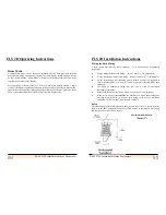
The maximum diameter of the plug (WHICH MUST NOT BE REMOVED) is 20mm,
which may be a consideration when planning your cable run or if you need to cut a
hole in a bulkhead. Please do not cut the cable.
If the cable is too long ,neatly coil up the excess in a convenient location. If the cable
is too short then contact us as we can supply 10m extension cables. Please do not cut
the cable.
You can use a maximum of two extension cables giving a maximum length of 30m. It
should be noted that each extension cable will cause a slight reduction in perform-
ance. Please do not cut the cable.
Every transducer is tuned to work with its own cable, as such cutting and rejoining the
cable can have serious implications as to the performance and accuracy of your FLS
system:
·
NEVER CUT THE TRANSDUCER CABLE
9
FLS 2D Instruction Manual
FLS 2D Operating Instructions
This is the distance from the boat’s bow to the transducer position and allows the
user to obtain a more realistic picture of the seabed with respect to the vessel.
Language
Allows one of the currently available languages to be selected for unit operation.
Depth Units
Units can be set to Metres or Feet.
Depth Offset
The Depth Offset can be set from -3.0m to +3.0m. If the offset is positive, the set
offset will be added to the calculated depth below transducer to give depth below
the surface If the offset is negative, the set offset will be subtracted from the
calculated depth below transducer to give depth below the keel.
This offset only applies to the digital depth readout in the bottom left hand corner of
the display and NOT the graphical seabed picture.
Operating a Repeater Unit
A repeater display unit is different to a master display it is missing the connection
for power. Repeaters can only be driven by display that are repeater enabled. These
displays have a third plug marked repeater, in the normal display this plug is
blanked.
It should be noted that changing range on a repeater unit will be independent of the
master unit so they may both be on different ranges (unless both units are set to
Auto Range). However, it is the range selected on the master unit that will dictate
the transmission pulse length set by the transmitter circuit.


