MVS3 Operator's Manual
Revision 1
This manual is intended for use with ECHOlab's model MVS3 broadcast television
switcher, with software version 4.x and higher. Last manual revision: 08-30-96
Страница 1: ...MVS3 Operator s Manual Revision 1 This manual is intended for use with ECHOlab s model MVS3 broadcast television switcher with software version 4 x and higher Last manual revision 08 30 96...
Страница 2: ...fills 9 4 What about signal formats 10 5 How about options 11 6 My control panel shows DISCONNECTED 11 7 The serial editing interface does not work 11 8 How do the GPI s work 12 9 How do I adjust subc...
Страница 3: ...INTRODUCTION page 3 Ramp generators 39 Rotary wipes 40 Calibration registers 41 Post production 42 PROGRAMMING 43 Setups 43...
Страница 4: ...erboard holds the genlock sync card an optional card is available for chromakey it is also installed as a daughterboard on the lower card The chassis assembly includes a motherboard and a switching po...
Страница 5: ...are mounted on the CPU card They should be changed at two year intervals and replaced ONE AT A TIME so no voltage interruption results If the unit is continuously powered the batteries can be changed...
Страница 6: ...ard 4 optional zero timed terminating video inputs are available for any synchronous NTSC or monochrome source composite preferred or non composite One DSK FILL input is also available for key fill in...
Страница 7: ...e edges and corners For this use the signal is nominally 1v p p but in practice a keyer gain of ten or more is used to clean up imperfections in the black and white areas This means that the middle te...
Страница 8: ...can be modified with the appropriate SYMM BORDER and CLIP knobs Alternately the selected cal value the active cal value will have a carat to it s left can be trimmed with the and keys For example com...
Страница 9: ...phase is set by the relative position of burst phase and horizontal phase Assuming the reference is in correct SCH phase if the above calibrations have been performed correctly the MVS should be in c...
Страница 10: ...y changing a command and CPU board jumpers on revision D and later providing you have a sufficient number of video boards in the MVS one for composite two for Y C and three for component Please note t...
Страница 11: ...power The MVS chassis has a power switch that is accessed by hinging open the chassis door It should be on and illuminated Check that the chassis CPU board is running There is a bank of four LED s on...
Страница 12: ...lected to what you believe it is Often this dicrepancy is the problem Check the cable About half the interface problems are traced down to a mis wired or incorrect cable Is the editor GVG 100 protocol...
Страница 13: ...the difference in frequency of the MVS as horizontal frequency in internal mode is counted down from internal subcarrier frequency This procedure works for composite Y C or component systems Adjust C...
Страница 14: ...gy for using the MVS open collector tally outputs The tally connections function by providing an open collector output that provides a short to ground when selected 1 2 amp 30V max TALLY CONNECTOR INT...
Страница 15: ...tor marked GPIO The pinout for this connector is shown below The GPO and tally connections function by providing an open collector output that provides a short to ground when selected 1 2 amp 30V max...
Страница 16: ...lost or the batteries are dead The calibration register contents have been lost Replace the batteries if required restart and recalibrate if necessary Calibration register settings as shipped can be...
Страница 17: ...lab with the ID number of your MVS3 and a purchase order number Command 24 displays your unique ID number ECHOlab will then give you a nine digit number that will install your desired option key this...
Страница 18: ...PRODUCTION page 18 PRODUCTION Video Functional Diagram...
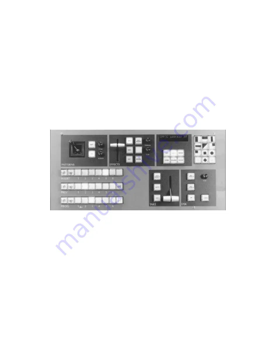
Страница 19: ...and programming operations A numeric keypad is used for entering wipe patterns digital rates colors and other data Control Panel With video signals connected to at least inputs one and two and approp...
Страница 20: ...5 5 Key 5 DskCut Cgen 6 Cgen DskCut Ckey 7 Chromakeyer DskCut Insrt 8 Insert bus Note that if the cut select choice is not in the display the first push of the cut select button will display the curre...
Страница 21: ...s key is selected the clip level will be correct DSK COLOR To change the color used for the DSK matte fill press the COLOR button located beneath the display until the DSK color is displayed The displ...
Страница 22: ...buttons Or key in a new rate in seconds and frames using the numeric keypad and press the RATE button again If a rate is keyed in as frames only in the range 1 99 it will be converted to seconds and f...
Страница 23: ...take is paused and the AUTOTAKE lamp blinks The take may be resumed by pressing AUTOTAKE again or it may be completed manually MANUAL TAKE The manual lever can be used instead of the AUTO TAKE If a m...
Страница 24: ...ut either of the other two colorizers can be selected for use with Command 32 See details in the Commands section of the manual TAKE SELECT Press TAKE SELECT to display all the options available for t...
Страница 25: ...will light on the preview bus to indicate that the effects section is being used on the preview screen If AUTOTAKE is used to bring the preview picture to the program screen the EFF button on the pre...
Страница 26: ...color is displayed The display will show saturation luminance and hue as Bdr ss ll hh Change the border color by holding down the COLOR button with BDR displayed and adjusting the three SYMM BORDER C...
Страница 27: ...s out or simply adjust any other control on the panel For instance press CLEAR 3 In NORMAL mode the bordered pattern will appear first as a small square and grow to fill the screen if the REVERSE butt...
Страница 28: ...mix control lever WIPE When the WIPE button is pressed the MIX button goes out and the lever wipes in the selected pattern If the mix lever was in an intermediate position that level of mix remains on...
Страница 29: ...Key Source KEY1 1 KEY1 BNC KEY2 2 KEY2 BNC KEY3 3 KEY3 BNC KEY4 4 KEY4 BNC KEY5 5 KEY5 BNC CGEN 6 CGEN BNC CKEY 7 RGB BNC s INSRT 8 INSERT BUS For instant access to say Key3 press 3 on the numeric ke...
Страница 30: ...rate is not currently in the display when the button is pressed the rates will be cycled through starting with fade to black DSK autotake effects key rate and lastly the recall panel rate To change a...
Страница 31: ...on 13 Set controls to panel values 14 Unused 15 Set GPI4 mode autotake dsk black recall panel 16 Set chromakeyer highlighting 00 thru 99 17 Set SMPTE protocol 38400 9600 bps odd even no parity 18 Set...
Страница 32: ...numeric keypad use the and keys to change the current character and use the 0 key to step to the next character Press the CLEAR button to terminate the process 4 Display revision and options Software...
Страница 33: ...blink on and off with various rates from 5 to 30 frames 12 Set DSK reverse Allows keying on white letters instead of black 13 Set controls to panel settings After some operations such as replaying st...
Страница 34: ...aid to communications troubleshooting 21 SMPTE transmit test Transmits test signals out the edit port when Command 21 is turned on Useful for debugging a serial comm link Make sure to turn it off whe...
Страница 35: ...r color but background or DSK color can be alternatively selected 33 Program 2 output If the POP programmable output option is installed this command will allow the user to select the function of the...
Страница 36: ...a take transition Note that the desired border color source is set using command 32 40 DSK preview Turn this command on to preview a DSK key on the DSK monitor This will allow a DSK key to be adjuste...
Страница 37: ...ges CLEAR when finished and turn calibration OFF with 100 COMM if you want to prevent accidental recalibration Comm Circuit SYMM BORDER CLIP 101 BGR color Null R Y Null B Y 102 BDR color Null R Y Null...
Страница 38: ...ughly 99 50 0 With a vectorscope on preview adjust all three colors to full saturation and zero degree phase with commands 114 and 116 Wipe center 104 Wipe DC Wipe size To adjust the command set up a...
Страница 39: ...knob Set horizontal blank width using the blank CLIP knob 10 7 uS is a typical value Circles 108 Circle Patt 32 Pat 8 H Pat 8 V View a circle wipe to adjust these offsets A small circle should be use...
Страница 40: ...to 500 b Press 117 COMM adjust the SYMM knob for centering note that the keys help fine trim c Select pattern 50 and adjust SYMM for centering The display Rtry xxx Bdr Clp will show you the contents o...
Страница 41: ...59 and 60 When you have finished with these calibrations test them with all rotary wipes If all wipes are good save user calibration values using Command 401 If calibration is disturbed later you can...
Страница 42: ...Connect a 9 wire cable with DB 9 connectors between MVS3 and edit controller Pin use is shown on p 13 of Installation 2 Enable edit controller for serial interface operation 3 Edits should now be perf...
Страница 43: ...he number before pressing RECALL PANEL Note that the SHIFT key must be held down before entering the setup number into the display RECALLING SETUPS To recall a setup enter its number 1 9 or 1 99 with...
Страница 44: ...rce on PREV Select pattern 6 and press EFF on the PREV bus then select an insert bus fill source 2 Hold down the SHIFT key and then press 1 RECALL PANEL This will save the square as panel 1 3 Select P...