7
Removing Crossover from Speaker
1.
Lie the speaker on its back and remove the woofer by carefully loosening the screws
(don’t let the screwdriver slip and damage your cone or surround!) and lifting it gently out
of the cabinet.
2.
Disconnect the two wires (green and green/black stripe) from the woofer and place the
woofer off to the side in a safe location.
3.
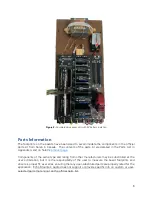
You will now be able to see the stock crossover unit mounted to the rear wall of the
speaker. Now is a good time to take a picture of the stock units, wire orientation, etc., in
case you ever want to return the speaker to its stock configuration. Your new Echo
Mountain boards use the same pad numbering convention (E1, E2, E3, etc.) as the factory
boards for simplicity and ease of rework.
4.
Unscrew the six Philips head screws that secure the mounting plate to the rear wall of
the speaker and set them aside in a safe place.
5.
At this point, you’ll need to disconnect the wires going to the crossover unit in order to
be able to remove it from the cabinet. There are two options for this: de
-
soldering the
wires at the PCB (difficult because of the limited access through the woofer cutout), or
snipping the wires at the PCB (and then de
-
soldering the small bits of remaining wire once
the unit is removed). We strongly recommend the latter method, as it’s much easier, and
there is enough slack in the wires to allow for this. Snip the wires as close to the PCB as
possible (they should all be accessible from the top side of the board).
6.
Once the wires are de
-
soldered or cut from the PCB, you will need to remove them from
the strain relief “clamp” that is adhered to the crossover mounting plate. This strain relief
apparatus doesn’t look the same on every model, but usually consists of adhesive, a zip
tie, or both. The adhesive is brittle enough due to years of age that it can be easily broken
and removed. Don’t worry about damaging the strain relief clamp, as you’ll be replacing
it later with an adhesive
-
backed zip tie mount and zip tie, but do take care not to damage
the wires.
7.
At this point, the crossover assembly should be free of the speaker, and you should be
able to remove it through the woofer cutout.
8.
Repeat steps 1
-
7 above for the other speaker.
Removing Factory PCB from Crossover Unit
1.
Place the crossover unit on your workbench, and carefully release the PCB from the four
snap
-
lock plastic terminals by gently (gently!) pinching on the tabs with a pair of non
-
marring pliers or your fingers. Do this to one corner at a time.
2.
Once the PCB is free of the clips, locate the red and black wires connected between the
crossover binding posts and the PCB, and de
-
solder these wires from the PCB (leaving
them connected at the binding posts).
3.
Locate the two wires coming from the inductor mounted on the crossover plate to the
PCB, and de
-
solder these wires from the PCB.
4.
The factory PCB should now be free of the rest of the crossover assembly; set it aside.
5.
Repeat steps 1 through 4 above for the other crossover unit.
Содержание JBL 4425
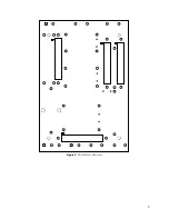
Страница 5: ...5 Figure 2 PCB bottom side view...


