background image

920-5203-00 Rev. B

Page 6 of 12

Bracket Installation:

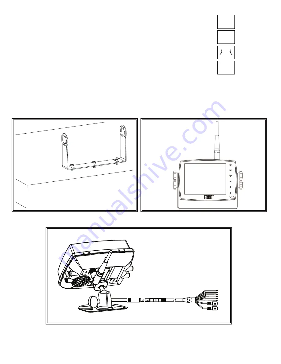
Installation instruction of using U-support bracket

1. Select suitable position on vehicle and fix the U-support bracket with screws (Figure 4)

2. Fix the monitor to the U-support bracket with angle adjustment screws and adjust the view angle of the monitor (Figure 5)

3. Connect the monitor with the AV and power supply conversion cable (Figure 6)

Figure 4

Figure 5

Figure 6

Reversing Display:

1. When the white wire is connected to the positive wire of the left turn light , the monitor automatically

    switches to CAM1 (left side camera) when the left turn indicator is activated.

2. When the blue wire is connected to the positive wire of the right turn light, the monitor automatically

    switches to  CAM2 (right side camera) when the right turn indicator is activated.

3. When the brown wire is connected to the positive wire of back-up light, the monitor automatically 

    switches to  CAM 3 (back-up camera) when the back-up light is turned on. The distancing grid will 

    also be displayed.

4. When the green wire is activated, the monitor automatically switches to CAM4.

CAM1

CAM2

CAM4

Содержание Gemineye

Страница 1: ...esult in property damage serious bodily personal injury and or death to you and those you are seeking to protect 920 5203 00 Rev B Page 1 of 12 Installation Instructions Wireless Camera Monitor System...

Страница 2: ...0 6 D 160 5mm W x114 6mm H x27mm D Operating Temp 20 C to 70 C 4 F to 158 F RH90 Storage Temp 30 C to 80 C 22 F to 186 F RH90 Precautions Storage and Keeping 1 Do not expose the monitor to excessive h...

Страница 3: ...ss camera input 1video output and 1 audio output 8 Operates from 10 32V Supports 12V or 24V vehicle systems 9 On board speaker 10 Automatic scanning function 11 The scale can be adjusted for left righ...

Страница 4: ...ill holes according to the size of U bracket and fix the U bracket 3 Drill a 3 4 19mm hole next to U bracket 4 Install the camera on U bracket 5 Connect the camera tail with the extension cable from i...

Страница 5: ...wire to GND Single brown wire to positive power wire of back up light Single white wire to positive power wire of left light Single blue wire to positive power wire of right light Single green wire to...

Страница 6: ...e wire is connected to the positive wire of the left turn light the monitor automatically switches to CAM1 left side camera when the left turn indicator is activated 2 When the blue wire is connected...

Страница 7: ...e position on vehicle and fix the base support Figure 7 2 Fix the monitor to the base support and adjust the view angle Figure 8 3 Connect the monitor with the AV and power supply conversion cable Fig...

Страница 8: ...nnel Selection Press to select the lower setting or display the scale Press to decrease brightness Press to increase brightness MENU Press to show menu Mode Picture Mode Press to select different pict...

Страница 9: ...rs to the reversing distance indicator displayed on the monitor 920 5203 00 Rev B Page 9 of 12 Menu Press MENU to display the following options and settings Picture Option System Auto Scan and Set up...

Страница 10: ...e PAIRING function the screen will display PAIRING START It counts down 50 seconds Press to select OFF ON Long press the PAIR on the camera for 5 seconds The screen shows SAVE DATA and picture then co...

Страница 11: ...o set proper orientation No reversing function i e Picture The black wire of the monitor AV cable to the reversing light may be loose The red wire from the monitor may be loose This device complies wi...

Страница 12: ...THE IMPLIED WARRANTIES FOR MERCHANTABILITY OR FITNESS FOR A PARTICULAR PURPOSE ARE HEREBY EXCLUDED AND SHALL NOT APPLY TO THE PRODUCT BUYER S SOLE AND EXCLUSIVE REMEDY IN CONTRACT TORT OR UNDER ANY O...

Отзывы: