background image

EC-VP-1100 User Manual – V1


- 10 -


5.3 

Install the Optional Peripheral 


5.3.1 Install the MSR


1. 

Remove the left side screw 

2. 

Connect the MSR 


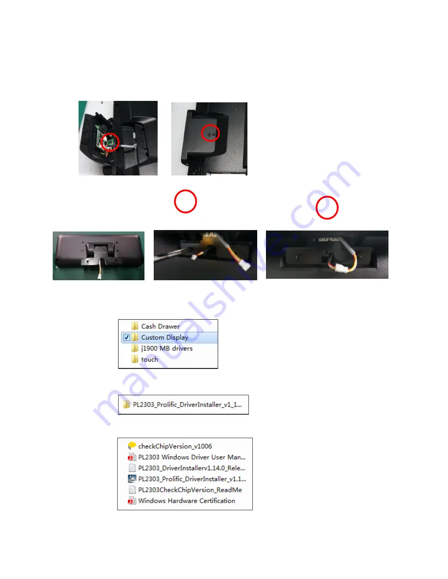
5.3.2 Install the Customer Display (Physically and Driver) 

1. 

  Fix the customer display with two screws 

2. 

  Connect the cable 


3. Install the driver 

3.1 Open the installer directory in the CD, select the J1900 MB drivers


3.2  Double-

click the “custom display” to proceed 


3.3 Double-

click “setup.exe” to start installation 


3.4 When installation starts, click [NEXT] to proceed to the next step, until installation finish 

Содержание EC-VP-1100

Страница 1: ...User Manual EC VP 1100 All in one Touch POS Terminal...

Страница 2: ...MSR 10 5 3 2 Install the Customer Display 10 5 3 3 Install the Second Display 11 5 3 4 Connect the Cash Drawer 11 6 INSTALLATION THE DRIVERS AND SOFTWARE 12 14 6 1 Install the Touch Screen Driver 12 1...

Страница 3: ...BLE UNITS FRUS 17 8 1 Safety and Precautions 17 8 2 Before You Begin 17 8 3 Replace Parts 17 8 3 1 Rear Cover 18 8 3 2 MSR 18 8 3 3 Customer Display 18 8 3 4 SATA Interface 18 8 3 5 Mainboard 19 8 3 6...

Страница 4: ...any objects into the ventilation holes It may cause short circuit for the internal components and cause a fire or electric shock After the computer is stored below temperature of 10 degree put the ma...

Страница 5: ...quirements of EU Council Directive 89 336 EEC on the approximation of the laws of the Member States relating to electromagnetic compatibility Logic Controls cannot accept responsibility for any failur...

Страница 6: ...R Reserved 1 X TOUCH Reserved 1 X 12V DC Input 1 X 12V DC Out VGA Signal LVDS Operation System Windows 7 POSReady 7 Windows 8 1 Windows Embedded 8 1 industry Windows 10 LCD Panel Viewing Area 15 Inche...

Страница 7: ...A Compliant 100mm X 100mm Optional Glass Strengthen Glass For Non Touch Version Dimension 350W 211D X 344H mm Weight NW 4 5KG GW 6 5KG Optional Peripherals 3 Tracks Magnetic Reader Support 1 line VFD...

Страница 8: ...EC VP 1100 User Manual V1 7 4 Installation Guide 4 1 Appearance 4 2 Power Button...

Страница 9: ...al output for connection of external VGA monitor COM2 3 For connection of serial devices USB2 0 Connection to USB 2 0devices compatible with USB 1 1 devices USB3 0 Connection to USB 3 0devices compati...

Страница 10: ...X 1 Warranty sheet X 1 Drivers CD X 1 If any of the above item is missing please contact you dealer After unpacking the carton connect the power cord and Ethernet extension cable properly to the syste...

Страница 11: ...Physically and Driver 1 Fix the customer display with two screws 2 Connect the cable 3 Install the driver 3 1 Open the installer directory in the CD select the J1900 MB drivers 3 2 Double click the c...

Страница 12: ...5 3 3 Install the Second Display 1 Turn the second display secure the stand with four screws 2 Connect the power to power output and VGA cable 5 3 4 Connect the Cash Drawer 1 Connect the cash drawer...

Страница 13: ...driver 1 Touch Screen Driver Installation Step 1 Open the installer directory in the CD select J1900 MB drivers Step 2 Double click the eGalaxTouch_5 11 0 9126 to proceed Step 3 Double click setup exe...

Страница 14: ...PS 2 click NEXT to continue installation Step 6 Select install RS232 interface driver and click Next to continue Step 7 Select option NONE click Next to continue installation Step 8 When installing U...

Страница 15: ...10 Select the destination location to install the touch driver The default path is C Program Files eGalaxtouch Click Next to continue installation Step 11 Select the Program Folder to install the util...

Страница 16: ...eck the touch screen cabling 3 Check the cabling form mainboard to LCD 4 Check the BIOS setting 7 4 Power Failure Power shut down unexpectedly cannot turn on the system 1 Check the power cable 2 Check...

Страница 17: ...le 2 Replace the cash drawer cable 7 9 Re Boot Continuously 1 Restore the BIOS defaults 2 Remove all I O device drivers and reinstall them 3 Check the IDE cable 4 Check the memory 7 10 Printer Doesn t...

Страница 18: ...y FRU To prevent static damage to components wear a grounded wrist strap Alternatively discharge any static electricity by touching the bare metal chassis of the unit case or the bare metal body of an...

Страница 19: ...2 Remove the hard disk 3 Remove the cover 8 3 2 MSR 1 Remove the screws 2 Disconnect the cable 3 Remove the MSR 8 3 3 Customer display 1 Disconnect the cables 2 Remove the customer display with two s...

Страница 20: ...After take out the mainboard pull from both side of the memory slot 8 3 7 The LCD panel 1 Remove the mainboard and radiator s screws total 8 screws 2 Disconnect the cables 1 Tear up the black lid 2 Di...

Страница 21: ...EC VP 1100 User Manual V1 20 9 Mainboard...

Страница 22: ...EC VP 1100 User Manual V1 21...

Страница 23: ...EC VP 1100 User Manual V1 22 Manufacturer EC LINE Thank you very much for using EC Line product For service please contact service ecline com hk www eclinepos com...

Отзывы: