Chengdu Ebyte Electronic Technology Co., Ltd.
E810-TTL-CAN01 User Manual
Co
Copyright ©2012–2019
,
Chengdu Ebyte Electronic Technology Co., Ltd.
21
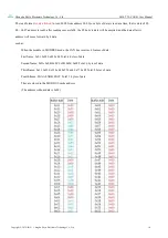
And send up to 8 bytes of data at a time:
Write 8 bytes of data by writing a command: 01 10 00 00 00 08 10 00 11 00 22 00 33 00 44 00 55 00 66
00 77 00 88, write this command to a special tool (Modbus CRC 16 calculator), Calculate the CRC check value
and add it to the instruction: 01 10 00 00 00 08 10 00 11 00 22 00 33 00 44 00 55 00 66 00 77 00 88 FE D5, sent
in HEX format, can write 8 bytes Data, when successfully written, will send the written data to the CAN bus,
that is, the CAN bus will send 8 bytes of data: 0x11, 0x22, 0x33, 0x44, 0x55, 0x66, 0x77, 0x88. In the CAN
message, the frame information and the frame ID are configured by the user in advance.
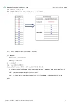
It is not allowed to send in an instruction format.as follows: 01 10 00 00 00
09 12
00 11 00 22 00 33 00 44
00 55 00 66 00 77 00 88
00 99
5 Operation Instructions
5.1 Entering Command Configuration Instructions
Note: In the normal working mode, the mode indicator flashes at 1Hz frequency; when entering the
command configuration mode, the indicator light flashes at 5Hz frequency. Whether it is software entry or
hardware entry, the configured parameters are valid after reset.
There are two ways to enter the command configuration mode:
1 Switching from other modes to command mode (software entry):
The serial device continuously sends "+++" to the module. After the module receives "+++", the 3 second
timer expires and starts to start. If any AT command is received within the timeout period, it will successfully
switch to the configuration mode (after entering, The module indicator flashes at a frequency of 5 Hz).
At this point, the parameters can be configured. For the parameter list and parameter description, please
refer to the following.
After the parameter configuration is successful, the serial device sends the command "AT+ EXAT" to the
module. After receiving the command, the module returns "+OK" and exits the configuration mode and
returns to the pre-configuration mode. Then short-circuit the reset RESET pin and the parameters take effect.
It is also possible to reset the module with the command "AT+REBT" after successful configuration with the
AT command parameters.
2 Switching from other modes to command mode (hardware entry):
Short-circuit the CFG pin to GND to enter the configuration mode directly. (After entering, the module
indicator flashing frequency becomes 5Hz. During the configuration process, the CFG pin must be kept low
for all times.) Send the AT command directly for configuration. After shorting and shorting, short reset the
RESET pin and the parameters take effect.
Remark: Both the hardware entry command mode and the exit command mode have higher priority than the
software command entry command mode.
For example, first use the software command to enter the command mode, and then short the CFG pin to
GND. Because the hardware priority is high, it is now regarded as the hardware entry command mode. When
the CFG pin goes high, it is directly the hardware exit. Command mode.


