Copyright ©2012–2021
,
Chengdu Ebyte Electronic Technology Co.,Ltd.
9
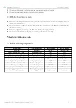
Please ensure the humidity is within limited range, some parts are sensitive to humidity
Please avoid using modules under too high or too low temperature.
6.3 BER(Bit Error Rate) is high
There are co-channel signal interference nearby, please be away from interference sources or modify frequency and
channel to avoid interference;
The clock waveform on SPI is not standard, check whether there is interference on the SPI line, and the SPI bus line
should not be too long;
Poor power supply may cause messy code. Make sure that the power supply is reliable;
The extension line and feeder quality are poor or too long, so the bit error rate is high.
7 Guide for Soldering work
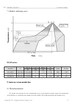
7.1 Reflow soldering temperature
Profile Feature
Curve characteristics
Sn-Pb Assembly
Pb-Free Assembly
Solder Paste
Solder paste
Sn63/Pb37
Sn96.5/Ag3/Cu0.5
Preheat Temperature min
(
Tsmin
)
Min preheating temp
100℃
150℃
Preheat temperature max (Tsmax)
Mx preheating temp
150℃
200℃
Preheat Time (Tsmin to Tsmax)(ts)
Preheating time
60-120 sec
60-120 sec
Average ramp-up rate(Tsmax to Tp)
Average ramp-up rate
3℃/second max
3℃/second max
Liquidous Temperature (TL)
Liquid phase temp
183℃
217℃
Time
(
tL
)
Maintained Above
(
TL
)
Time below liquid phase line
60-90 sec
30-90 sec
Peak temperature
(
Tp
)
Peak temp
220-235℃
230-250℃
Aveage ramp-down rate
(
Tp to Tsmax
)
Aveage ramp-down rate
6℃/second max
6℃/second max
Time 25℃ to peak temperature
Time to peak temperature for
25℃
6 minutes max
8 minutes max


