


hengdu Ebyte Electronic Technology Co.,Ltd.
Copyright ©2012–2020
,
Chengdu Ebyte Electronic Technology Co.,Ltd.
5
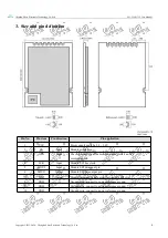
3. Size and pin definition
Pin No.
Pin item
Pin direction
Pin application
1
VCC
-
Power supply must be 2.3 ~ 3.6V
2
CE
Input
Module control pin
3
CSN
Input
The chip select pin of the module is used to start an SPI
communication.
4
SCK
Input
Module SPI bus clock
5
MOSI
Input
Module SPI data input pin
6
MISO
Output
Module SPI data output pin
7
IRQ
Output
Module interrupt signal output, low level is effective.
8
GND
-
Ground wire, connect to power reference ground.
9
GND
-
Ground wire, connect to power reference ground.
10
GND
-
Ground wire, connect to power reference ground.