background image


7. 

7. 

Specification                                                           


Chapter 8 

29

Содержание EZPPC70-2B-C1G

Страница 1: ...User s Manual EZPPC70 2B C1G EZPOS70 2B C1G...

Страница 2: ...erates uses and can radiate radio frequency energy and if not installed and used in accordance with the instructions may cause harmful interference to radio communications However there is no guarante...

Страница 3: ...96 EC concerning waste electrical and electronic equipment WEEE The Directive determines the framework for the return and recycling of used appliances as applicable throughout the European Union This...

Страница 4: ...n 6 3 3 Adjust View Angle EZPOS Series only 8 3 4 Wall Mount Kit installation EZPC Series only 9 3 5 Turn on the Device 10 4 Driver and Utility Installation 11 4 1 Before the installation 11 4 2 Chips...

Страница 5: ...ound 22 Feedback Sound Option 22 Tone 23 Duration 23 5 6 Screen Calibration 23 4 points mode 1 24 4 points mode 2 24 How to Use Event Selector 25 6 I O Definition 26 6 1 Power Connector 26 6 2 Serial...

Страница 6: ...ssis 4 x USB 2 0 4 x RS 232 Gigabit Ethernet port RJ 45 cash drawer port RJ 11 and 1 X parallel port equipped Video Module Optional Wireless LAN supported Microsoft Windows series operation system Win...

Страница 7: ...erify that the box contains the following items 1 Device X 1 2 Wall mount Kit x 1 EZPPC series only 3 Power Adaptor X 1 4 Power Cord X 1 5 Driver and utility CD X 1 6 Base Unit EZPOS series only 7 D S...

Страница 8: ...Tour Front View LED Indicator The Power indicator will glow green when power is on The HDD indicator will blink green when the HDD is accessed The LAN indicator will blink green when transferring dat...

Страница 9: ...Back View Back Panel I O Note For details of I O ports on the back panel please refer to Chapter 6 I O Definition Chapter 3 4...

Страница 10: ...SB Keyboard and USB ODD Connect your USB Mouse USB Keyboard and USB ODD to USB ports on the back panel of the device LAN Cable Connect one end of RJ 45 LAN cable to the LAN port on the back panel of t...

Страница 11: ...the female connector of the D Sub 9 cable to the COM port on the back panel of the device in the correct orient MSR Installation 1 Remove the two plastic covers from the device as shown below 2 Loosen...

Страница 12: ...3 Pass the MSR cable through the hole of the chassis as shown below 4 Plug the MSR to the connector in the correct orient 5 Tighten the four screws of the MSR assembly as shown below Chapter 3 7...

Страница 13: ...6 Close the back panel and tighten the four screws on the back panel 7 Finished 3 3 Adjust View Angle EZPOS Series only Adjust the device to the proper view angle Chapter 3 8...

Страница 14: ...3 4 Wall Mount Kit installation EZPC Series only 1 Separate the wall mount kit 2 Align the screw holes of the wall mount kit to the holes of the device and tighten the four screws Chapter 3 9...

Страница 15: ...3 5 Turn on the Device 1 Make sure all peripherals are connected properly 2 Press and hold the power switch until the power indicator on the front panel glow green Chapter 3 10...

Страница 16: ...low are based on Microsoft Windows XP 1 Connect an external USB CDROM drive to the USB port and insert the driver CD and turn on the device The program autoruns and displays the DRIVER BANK screen 2 C...

Страница 17: ...2 Click Next 3 1 Click Next 3 2 Read the License Agreement carefully and click Yes 4 Click Next Chapter 4 12...

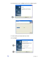
Страница 18: ...5 1 Select restart your computer right now or later 5 2 Click Finish 4 3 VGA Driver Installation 1 Click Graphic Driver 2 Click VGA Driver for WIN2K XP Chapter 4 13...

Страница 19: ...er files extracted click Next on the welcome screen 4 Read the License Agreement carefully and click Yes and then the installation starts 5 1 Select restart your computer right now or later 5 2 Click...

Страница 20: ...4 4 LAN Driver Installation 1 Click RTL81x0 LAN Driver On the welcome screen click Next Click Install to begin the installation 3 Click Finish Chapter 4 15...

Страница 21: ...4 5 Audio Driver Installation 1 Click AC 97 Audio Driver 2 Configures new software installation 3 Click Configure Anyway Chapter 4 16...

Страница 22: ...4 AC 97 drivers begins to install 5 1 Select restart your computer right now or later 5 2 Click Finish 4 6 Wireless LAN Driver Installation 1 Click Wireless Lan Driver Chapter 4 17...

Страница 23: ...2 On the welcome screen click Next and then the installation begins 3 1 Select restart your computer right now or later 3 2 Click Finish Chapter 4 18...

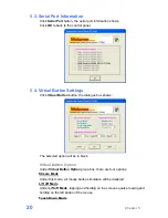
Страница 24: ...ting dialogue box c Feedback Sound Open the feedback sound setting dialogue box d Power Save Open the power down timer adjustment dialogue box e Calibration Switch to calibration screen f Calibration...

Страница 25: ...ton the dialogue box shows The selected option will be in black Virtual Button Option Under Virtual Button Option group box there are four options Stream Mode Under this mode all mouse button simulati...

Страница 26: ...will be enabled and show on the left bottom corner of the screen Automatic Mode Manual Mode Drop down List If the Drag Drop Mode under Virtual Button Option group box is select the drop down menu bel...

Страница 27: ...menu shows The minimize value is 0 5 and maximum value is 5 This option defines how long the right button function will be off The minimize value is 0 5 and maximum value is 5 Click the drop down menu...

Страница 28: ...om the screen Tone Drag the bar to adjust the frequency of the sound effect The minimize value is 200 and maximum value is 5000 Duration Drag the bar to adjust how long the Beep sound will be The mini...

Страница 29: ...the center of Cross Mark e Repeat Step 2 Step4 to finish the calibration procedure 4 points mode 2 a The mark shows in the middle of the length of the screen b Follow the instruction in green to touc...

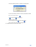
Страница 30: ...Yes to restore the old calibration click No How to Use Event Selector 1 On the desktop of Windows click icon 2 icon change to 3 Now the tapping is simulating right mouse button clicking 4 After one t...

Страница 31: ...ion about all I O ports as followings 6 1 Power Connector PIN Description PIN Description 1 19V 3 GROUND 2 19V 4 GROUND 6 2 Serial Port COM Port 1 2 3 4 PIN Description PIN Description 1 DCD 6 DSR 2 R...

Страница 32: ...N Description PIN Description 1 GND 6 N C 11 CTS 2 5V 7 N C 12 RTS 3 RXD 8 N C 13 DSR 4 TXD 9 RI 5V 12V 14 DCD 5 N C 10 DTR 15 N C 6 4 Cash Drawer Connector PIN Description PIN Description 1 GND 4 12V...

Страница 33: ...Cash Drawer Control Status Address Value Open 280H Bit 4 0 Close 280H Bit 4 1 Read Status 281H Bit 0 0 1 Chapter 6 28...

Страница 34: ...7 7 Specification Chapter 8 29...

Страница 35: ...S COM4 Internal Pin Header for MSR COM5 15Pin Header or DB9 COM6 Internal for Touch Panel Parallel 1 x DB25 ECP EPP SPP USB 4 x USB 2 0 LAN 1 x RJ45 Gigabit Ethernet Cash Drawer 1 x RJ11 12V Audio AC...

Отзывы: