background image


Copyrights 

©2009 All rights reserved. The information in this 

document is subject to change without prior notice in 

order to improve reliability, design and function and does 

not represent a commitment on the part of the 

manufacturer.  


This document contains proprietary information 

protected by copyright.    All rights are reserved.    No 

part of this manual may be reproduced by any 

mechanical, electronic, or other means in any form 

without prior written permission of the manufacturer.   


All trademarks are property of their respective 

owners 


Liability Disclaimer 

In no event will the manufacturer be liable for direct, 

indirect, special, incidental, or consequential 

damages arising out of the use or inability to use the 

product or documentation, even if advised of the 

possibility of such damages.   


Regulatory Information 

FCC Notices   


i

This equipment has been tested and found to comply 

with the limits for a Class B digital device, pursuant to 

Part 15 of the Federal Communications Commission 

(FCC) Rules. These limits are designed to provide 

reasonable protection against harmful interference in 

a residential installation. This equipment generates, 

uses, and can radiate radio frequency energy and, if 

not installed and used in accordance with the 

instructions, may cause harmful interference to radio 

communications. However, there is no guarantee 

that interference will not occur in a particular 

installation. If this equipment does cause harmful 

interference to radio or television reception, which 

can be determined by turning the equipment off and 

on, the user is encouraged to try to correct the 

interference by one or more of the following 

measures: 

• Increase the separation between the equipment 

and the receiver. 

• Connect the equipment into an outlet on a circuit 

different from that to which the receiver is connected. 

• Consult the dealer or an experienced radio or 

television technician for help. 

This device complies with Part 15 (B) of the FCC 

Rules. Operation is subject to the following two 

conditions:  

1) this device may not cause harmful interference 

and  

2) this device must accept any interference received, 

including interference that may cause undesired 

operation. 

NOTE: THE MANUFACTURER IS NOT 

RESPONSIBLE FOR ANY RADIO OR TV 

INTERFERENCE CAUSED BY UNAUTHORIZED 

MODIFICATIONS TO THIS DEVICE. SUCH 

MODIFICATIONS COULD VOID THE USER'S 

AUTHORITY TO OPERATE THE DEVICE.


CE Notice 


This device complies with 

EMC Directive 

2004/108/EC

 issued by the Commission of the 

European Community. 

Copyrights 

Содержание TM50-5B-VU

Страница 1: ...User s Manual TM50 5B VU...

Страница 2: ...s and can radiate radio frequency energy and if not installed and used in accordance with the instructions may cause harmful interference to radio communications However there is no guarantee that int...

Страница 3: ...96 EC concerning waste electrical and electronic equipment WEEE The Directive determines the framework for the return and recycling of used appliances as applicable throughout the European Union This...

Страница 4: ...e and Power cord 3 2 2 Adjust View Angle 4 2 3 Turn on the Device 5 Touch Panel Driver Installation 6 3 1 Before the installation 6 3 2 Touch Panel Driver Installation 6 Basic Setup and OSD 10 4 1 Bas...

Страница 5: ...1 Hardware Setup 1 1 Quick Tour Front View Refer to the diagram below to identify the components on the front panel 1 Power button 2 Arrow button 3 button 4 Menu Menu button Hardware Setup 1...

Страница 6: ...5 Select Auto Select Auto button Back View Back Panel I O Hardware Setup 2...

Страница 7: ...ne connector of the USB cable to the USB port on the back panel another connector to your POS device 2 Connect the one connector of the audio cable to the Audio in jack on the back panel another conne...

Страница 8: ...3 Connect the power cord to the AC inlet and the power source 2 2 Adjust View Angle Adjust the device to the proper view angle Peripherals Installation 4...

Страница 9: ...2 3 Turn on the Device 1 Make sure all peripherals are connected properly 2 Press the power button Peripherals Installation 5...

Страница 10: ...nect an external USB CDROM drive to the USB port of your POS device and insert the driver CD And then the DRIVER BANK screen shows 3 2 Touch Panel Driver Installation 1 Click TM515 Series 2 Click Touc...

Страница 11: ...4 Click Next 5 Click Next 6 Select an item according to your needs and then click Next 7 Click OK Touch Panel Driver Installation 7...

Страница 12: ...8 If you want to use Multi Monitor check the box and click Next 9 Click Next 10 Click Next Touch Panel Driver Installation 8...

Страница 13: ...11 The driver starts to install 12 Click OK Touch Panel Driver Installation 9...

Страница 14: ...playback by pressing the or buttons while the OSD menu is not displayed Next press the button to mute the sound or the button to reactivate it Shortcut for adjusting contrast and brightness You can ad...

Страница 15: ...y pressing the OSD button or 3 Press the SELECT OSD button in fig 4 to activate the selected function or associated submenu 4 Adjust the desired value using the respective OSD arrow keys or 5 Press th...

Страница 16: ...he default settings 9300 K 6500 K or sRGB D65 or enter your own custom RGB values Press the or button to select from among Red Green or Blue You may then adjust the color values by using the or button...

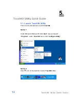
Страница 17: ...There are two alternatives to launch TouchKit Option 1 Under Microsoft Windows XP click start menu and select Programs under TouchKit menu click Configure Utility Option 2 Click icon on the task bar...

Страница 18: ...0 Whenever it finds a new TouchKit serial controller a new serial controller icon object will be shown in the controller list window automatically USB TouchKit device supports plug and play the icon o...

Страница 19: ...om EZPPC 70 Then this serial RS232 icon object in controller list window disappears automatically USB TouchKit device supports plug and play the icon object for USB controller will be shown in the con...

Страница 20: ...Release Check this check box to enable driver to generate a beep sound when touchecreen state is switched from touched state to untouched state Frequency Drag the slider to adjust this frequency to c...

Страница 21: ...ed as a double click event Double Click Area Double click area is used to set the double click area Change this value will affects the double click behavior for all of the mouse devices connected to E...

Страница 22: ...Touch without moving cursor With this mode the driver behaves similar as Click On Touch mode The cursor does not move to the touch position except the first touch point Click On Release without moving...

Страница 23: ...th multiple monitor system you need to do proper configuration to map the touchscreen working area to the correct system display area You can do such configuration with this property page shown as bel...

Страница 24: ...rey Map to main monitor when the system has only one monitor When the multiple monitor function was enabled and the system has only one monitor Driver allows user to generate the mouse event for the p...

Страница 25: ...The touchscreen will be mapped to the first quarter area of the specified monitor display Quarter 2 The touchscreen will be mapped to the 2nd quarter area of the specified monitor display Quarter 3 T...

Страница 26: ...ght X Axis and Y Axis In some cases if it is difficult to touch items at the edges of the touch panel you can set adjustment to reach the edges of the screen image Top If you set the Edge to Smaller T...

Страница 27: ...e to Smaller TouchKit will reduce the vertical position of the right edge If you set the Edge to Larger TouchKit will extend the vertical position of the right edge In some cases cursor will be behind...

Страница 28: ...to touch screen and cursor will be moved 10 pixel of X and Y Axis to right and top If you click 10 button the top bottom left and right edges will contract 10 of orientation to touch screen and curso...

Страница 29: ...Is the PC turned on see your PC s documentation Display Problems Image is displaced to the left right or to the top bottom If the image appears normal but off center you can adjust it using the OSD f...

Страница 30: ...If the colors are off e g white is not really displayed as white etc you should adjust the color temperature see Color Adjustment function in section OSD Menu Functions Troubleshooting 26...

Страница 31: ...7 Specification Specification 27...

Страница 32: ...Audio 1 x Audio Jack In w 2W Speaker x 2 I O Ports VGA 1 x DB 15 Power Input 100VAC 240VAC Input Wall Mount Support VESA Mount Color Black Compliance FCC CE WEEE RoHS BSMI C Tick Weight 5 kgs Dimensi...

Отзывы: