Operating instructions
K3G710-PV05-02
Translation of the original operating instructions
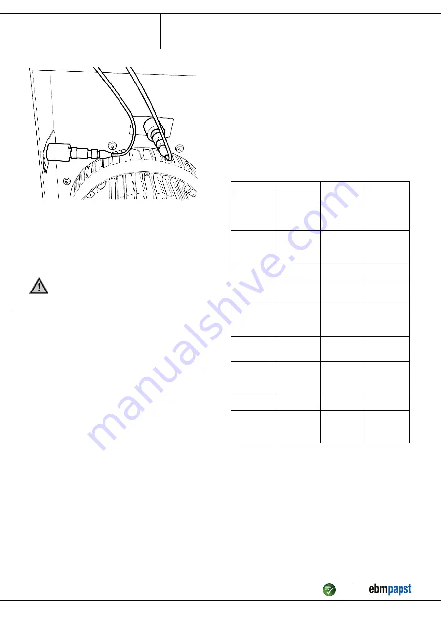
Fig. 5: Example illustrating vibration measurement. The arrangement of
the sensors depends on the device concerned and the installation
situation.
6.2 Cleaning
To ensure a long service life, check the fans regularly for proper
operation and soiling. The frequency of checking is to be adapted
accordingly depending on the degree of soiling.
DANGER
Risk of injury from rotating fan.
→ Only clean when not in motion. Do not disconnect the fan
from the power supply, just switch it off via the control input.
This will prevent start-up of the fan.
;
Dirt deposits on the motor housing can cause overheating of the motor.
;
Soiling of the impeller can cause vibration that will shorten the service
life of the fan.
;
Severe vibration can destroy the fan.
;
In such cases, switch off the fan immediately and clean it.
;
The preferred method of cleaning is dry cleaning, e.g. using
compressed air.
;
Do not use aggressive cleaning agents!
NOTE
Damage to the device during cleaning
Malfunction possible
→ Do not clean the device using a high-pressure cleaner.# Do
not use acid, alkali or solvent-based cleaning agents.
→ Do not use any pointed or sharp-edged objects for
cleaning.
;
Completely remove any cleaning agents used.
;
If severe corrosion is visible on load-bearing or rotating parts, switch
off the device immediately and replace it.
;
Repair of load-bearing or rotating parts is not permitted!
;
Operate the fan for 2 hours at maximum speed so that any water that
has ingressed can evaporate.
;
If cleaning does not eliminate vibrations, the fan may need to be
rebalanced. To have it rebalanced, contact ebm-papst.
;
The fan is equipped with maintenance-free ball bearings. The lifetime
lubrication of the ball bearings is designed for a service life of 40,000
hours.
;
If bearing replacement is necessary after that period, contact ebm-
papst.
;
Adapt the maintenance intervals to the actual level of dust exposure.
6.3 Safety inspection
NOTE
High-voltage test
The integrated EMC filter has Y capacitors. The tripping current
is exceeded when AC testing voltage is applied.
→ Test the device with DC voltage when you perform the
legally required high-voltage test. The voltage to be used
corresponds to the peak value of the AC voltage required by
the standard.
What to check
How to check
How often
What action?
Contact
protection
cover for
intactness or
damage
Visual inspection At least every
6 months
Repair or
replacement of
device
Device for
damage to
blades and
housing
Visual inspection At least every
6 months
Replacement of
device
Fastening the
cables
Visual inspection At least every
6 months
Fasten
Insulation of
cables for
damage
Visual inspection At least every
6 months
Replace cables
Impeller for
wear/deposits/
corrosion and
damage
Visual inspection At least every
6 months
Clean impeller
or replace device
Tightness of
cable gland
Visual inspection At least every
6 months
Retighten,
replace if
damaged
Condensation
drainage holes
for clogging,
where necessary
Visual inspection At least every
6 months
Open holes
Abnormal
bearing noise
acoustic
At least every
6 months
Replace device
Vibration test
Vibration tester,
start-up or
deceleration
measurement
Recommended
every 6 months
Clean impeller
or replace device
6.4 Disposal
For ebm-papst, environmental protection and resource preservation are
top priority corporate goals.
ebm-papst operates an environmental management system which is
certified in accordance with ISO 14001 and rigorously implemented
around the world on the basis of German standards.
Right from the development stage, ecological design, technical safety
and health protection are fixed criteria.
The following section contains recommendations for ecological disposal
of the product and its components.
Item no. 55980-5-9970 · ENU · Change 212420 · Approved 2020-02-17 · Page 14 / 15
ebm-papst Mulfingen GmbH & Co. KG · Bachmühle 2 · D-74673 Mulfingen · Phone +49 (0) 7938 81-0 · Fax +49 (0) 7938 81-110 · [email protected] · www.ebmpapst.com


