Operating instructions
K3G355-PV70-01
Translation of the original operating instructions
6.1.1 Warning codes
Number of pulses
Motor status - LED
orange
Message at status
relay
1
Current limitation in
action
2
Line impedance too
high (DC-link voltage
unstable)
3
Power limiter in action
4
Output stage
temperature high
5
Motor temperature high
6
Temperature inside
electronics high
7
DC-link voltage low
8
Braking mode: set in
case of external drive
in opposite direction
at high speed for
lengthy period
Yes
9
Calibration of rotor
position sensor in
progress
10
Actual speed is lower
than run monitoring
speed limit
Yes
11
Open circuit at analog
input or PWM input
for the set value
Yes
13
DC-link voltage high
15
Line voltage high
16
Shake-loose function
activated
6.1.2 Status codes
Manual reset by "Switch off line voltage - wait briefly - switch line
voltage back on" or, if provided,
via the "Fan enable/disable" input
Number of
pulses
Motor status -
LED red
Possible cause Possible
remedy
1
Phase failure or
line undervoltage
Missing phase
Poor power
supply quality
Check line
voltage
3
Output stage
overheating
Electronics
housing
contaminated
Provide better
cooling.
Manual reset
required
4
Communication
error between
master
controller and
slave controller
External
supply applied
via Vout for
setting
parameters.
Internal error
Switch off line
voltage
- wait -
switch back on
6
Motor
overheating
Ambient
temperature too
high
Impermissible
operating point
Reduce
ambient
temperature
Correct
operating point.
Manual reset
required
7
Hall sensor error Internal error
Switch off line
voltage
- wait -
switch back on
8
Motor blocked
Mechanical
blockage
Switch off
- check safe
isolation from
supply -
check
freedom of
movement of
rotor
9
Speed limit
exceeded
-
-
11
Rotor position
sensor
calibration error
Observe
ebm-papst
replacement
instructions
Rotor position
sensor
calibration
necessary.
Notify ebm-
papst
13
DC-link
undervoltage
Line voltage not
OK
Check the line
voltage applied.
6.2 Vibration testing
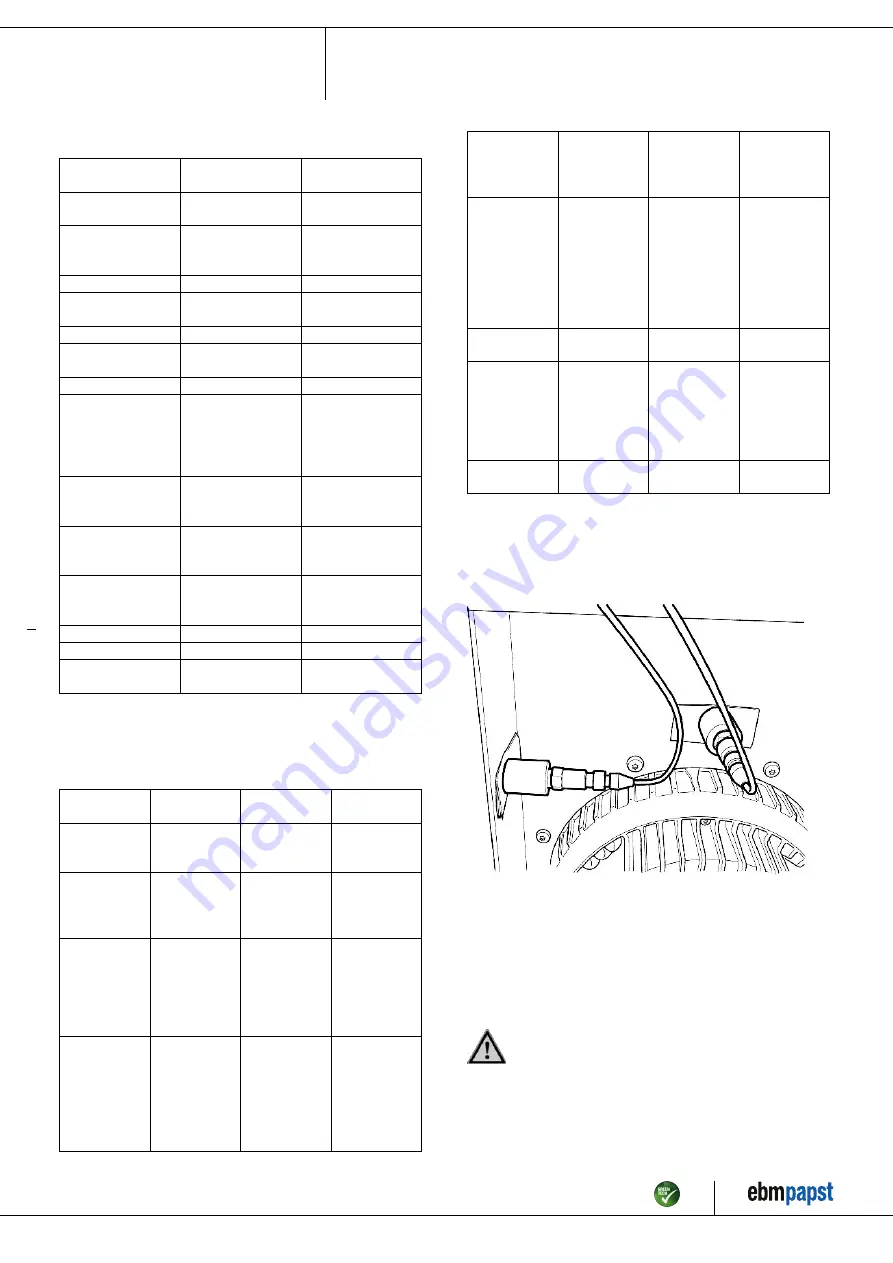
Checking of fan for mechanical vibration based on ISO 14694.
Recommendation: Every 6 months. Max. vibration severity is 3.5 mm/
s, measured at the motor fastening diameter on the motor support plate in
the direction of the motor axis of rotation and perpendicular to this.
Fig. 6: Example illustrating vibration measurement. The arrangement of
the sensors depends on the device concerned and the installation
situation.
6.3 Cleaning
To ensure a long service life, check the fans regularly for proper
operation and soiling. The frequency of checking is to be adapted
accordingly depending on the degree of soiling.
DANGER
Risk of injury from rotating fan.
→ Only clean when not in motion. Do not disconnect the fan
from the power supply, just switch it off via the control input.
This will prevent start-up of the fan.
;
Dirt deposits on the motor housing can cause overheating of the motor.
Item no. 57420-5-9970 · ENU · Change 220251 · Approved 2020-10-26 · Page 15 / 17
ebm-papst Mulfingen GmbH & Co. KG · Bachmühle 2 · D-74673 Mulfingen · Phone +49 (0) 7938 81-0 · Fax +49 (0) 7938 81-110 · [email protected] · www.ebmpapst.com


