

Operating instructions
K3G310-AZ88-02
Translation of the original operating instructions
6. MAINTENANCE, MALFUNCTIONS, POSSIBLE
CAUSES AND REMEDIES
Do not perform any repairs on your device. Return the device to ebm-
papst for repair or replacement.
WARNING
Terminals and connections have voltage even with a
unit that is shut off
Electric shock
→ Wait five minutes after disconnecting the voltage at all poles
before opening the device.
CAUTION
If control voltage is applied or a speed setpoint is stored,
the motor automatically restarts, e.g. after a power failure.
Danger of injury
→ Keep out of the danger zone of the device.
→ When working on the device, switch off the mains
supply voltage and secure the latter from being switched on
again.
→ Wait until the device stops.
→ After working on the device, remove any used tools or
other objects from the device.
If the device remains out of use for some time, e.g. when in
storage, we recommend switching the device on for at least
two hours to allow any condensate to evaporate and to move
the bearings.
Malfunction/error
Possible cause
Possible remedy
Impeller running
roughly
Imbalance in rotating
parts
Clean the device; if
imbalance is still
evident after
cleaning, replace the
device.
If you have
attached any weight
clips during cleaning,
make sure to
remove them
afterwards.
Motor does not turn
Mechanical blockage
Switch off, de-
energise, and
remove mechanical
blockage.
Mains supply
voltage faulty
Check mains supply
voltage,
restore power
supply.
Important! The error
message resets
automatically.
The device starts
up again
automatically without
advance warning.
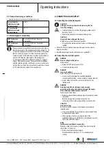
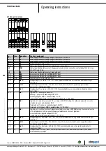
Faulty connection
De-energise, correct
connection, see
connection diagram.
Motor winding broken Replace device
Thermal overload
protector responded
Allow motor to cool
off, locate and rectify
cause of error, if
necessary cancel
restart lock-out
Insufficient cooling
Improve cooling. Let
the device cool
down.
To reset the error
message, switch off
the mains supply
voltage for a min. of
25 s and switch it on
again.
Alternatively, reset
the error message
by applying a control
signal of <0.5 V to
DIN1 or by short
circuiting Din1 to
GND.
Ambient temperature
too high
Reduce the ambient
temperature. Let the
device cool down.
To reset the error
message, switch off
the mains supply
voltage for a min. of
25 s and switch it on
again.
Alternatively, reset
the error message
by applying a control
signal of <0.5 V to
DIN1 or by short
circuiting Din1 to
GND.
Unacceptable
operating point (e.g.
counterpressure is
too high)
Correct the operating
point. Let the device
cool down.
To reset the error
message, switch off
the mains supply
voltage for a min. of
25 s and switch it on
again.
Alternatively, reset
the error message
by applying a control
signal of <0.5 V to
DIN1 or by short
circuiting Din1 to
GND.
Item no. 50655-5-9970 · ENG · Revision 82542 · Release 2014-05-08 · Page 11 / 12
ebm-papst Mulfingen GmbH & Co. KG · Bachmühle 2 · D-74673 Mulfingen · Phone +49 (0) 7938 81-0 · Fax +49 (0) 7938 81-110 · [email protected] · www.ebmpapst.com


