


EATON Vickers
Single, Double, Triple and Thru-drive Pumps Overhaul Service Manual V-PUVN-TS001-E October 2002
11
Section IV —
Installation and Operating
Instructions (cont.)
C. Shaft Rotation
General Data
Oil in a hydraulic system
performs the dual function of
lubrication and transmission of
power. It constitutes a vital
factor in a hydraulic system and
careful selection of it should be
made with the assistance of a
reputable supplier. Proper
selection of oil assures
satisfactory life and operation
of system components with
particular emphasis on
hydraulic pumps. Any oil
selected for use with pumps is
acceptable for use with valves
or motors.
See the Series 30 VMQ
product catalog for hydraulic
fluid guidelines.
Where special considerations
indicate a need to depart from
the recommended oils or
operating conditions, see your
Eaton representative.
Cleanliness
Clean fluid is the best
insurance for long service life.
Eaton recommends a fluid
cleanliness of ISO 18/16/13 or
better. To insure your hydraulic
system is clean, perform the
following steps.
1.
Clean (flush) entire new
system to remove paint, metal
chips, welding shot, etc.
2.
Filter each change of oil to
prevent introduction of
contaminants into the system.
3.
Provide continuous oil
filtration to remove sludge and
products of wear and corrosion
generated during the life of the
system.
4.
Provide continuous
protection of system from
entry of airborne
contamination, by sealing the
system and/or by proper
filtration of the air.
5.
Proper oil filling and
servicing of filters, breathers,
reservoirs, etc., cannot be
overemphasized.
6.
Good system and reservoir
design will insure that aeration
of the oil is kept to a minimum.
CAUTION
Pump shafts are
designed to be
installed in
couplings with a slip fit or very
light press. Pounding the
coupling on the shaft can ruin
the bearings. Shaft tolerances
are shown on the pump
installation drawings.
2. Indirect Drive.
Indirect drive
is not recommended for these
pumps.
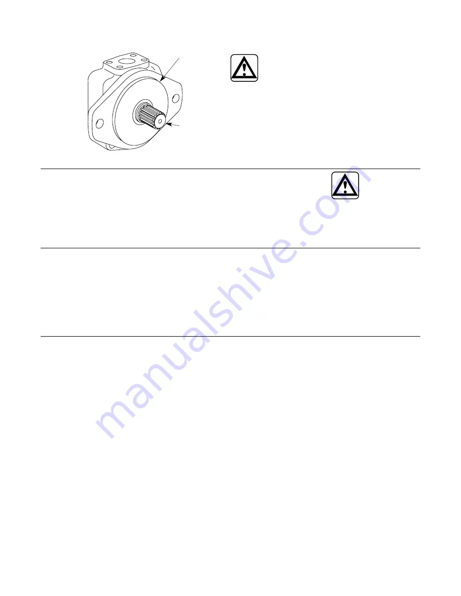
Figure 7.
Pilot Diameter
Pilot Diameter
Shaft
NOTE
Pumps are normally
assembled for right hand
(clockwise) rotation as viewed
from the shaft end. A pump
made for left hand rotation is
identified by an “L” in the
model code. (See Table 1)
NOTE
If it is desired to reverse the
direction of drive rotation, it is
necessary to disassemble the
pump and reverse the location
of the cartridge cam ring and
wafer plates. (See Section VI,
Part C)
CAUTION
Never drive a
pump in the wrong
direction of
rotation. Seizure may result,
necessitating extensive
repairs.
D. Piping and Tubing
1.
All pipes and tubing must be
thoroughly cleaned before
installation. Recommended
methods of cleaning are
sandblasting and wirebrushing.
2.
To minimize flow resistance
and the possibility of leakage,
use only as many fittings and
connections as necessary for
proper installation.
3.
The number of bends in
tubing should be kept to a
minimum to prevent excessive
turbulence and friction of oil
flow. Tubing must not be bent
too sharply. The recommended
radius for bends is three times
the inside diameter of the
tube.
E. Hydraulic Fluid Recommendations


