9
3. Inspect metering spool (12) and hydrostat (20) for
excessive wear, galling, erosion, and burrs. Remove burrs
with an India stone. If either of the spools are defective,
check body (30) bores for similar defects. Replace defective
parts.
4. Inspect check valve (26) for excessive wear, erosion
and burrs. The seat contact area of the valve should have a
bright circular contact area. Leakage paths across the check
valve will show up as a break in the bright circular area. Ero-
sion of the seat area may also cause a leakage path to de-
velop. If seat (27) requires removal, tap seat with an ap-
propriate thread, then install a length of threaded drill rod into
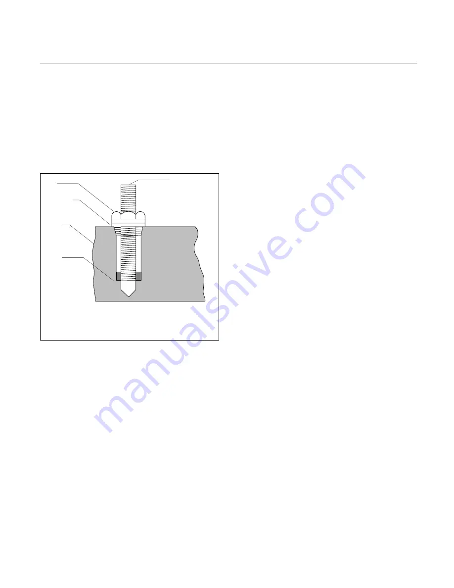
the seat. Remove seat from the valve body. See Figure 4.
Vise grip
pliers here
Nut
Washers
Valve
body
Seat
Thread seat with a suitable tap, then install a length of
threaded drill rod into seat. Install washers and nut, then
hold th the top of drill rod with vise grip pliers. Pull seat
from the valve by turning nut clockwise.
Figure 4. Removal of seat
5. Inspect springs (19) and (25) for excessive wear and
damaged coils. Replace springs if coils are damaged. In-
spect springs for distortion. The ends of each spring must be
parallel to each other. Replace springs if distorted.
6. Inspect body (30) for burrs, nicks, plugged passages
and porosity. If either the metering spool, hydrostat or check
valve are to be replaced, throughly inspect the bore from
which the part was removed for defects. If the metering
spool requires replacement, and the unit is a FCGT-02-A-11,
remove and replace sleeve (15) before installation of the
new spool. Clean up sleeve with an India stone before the
spool is installed to remove the possibility of the existance of
burrs. Burrs can prevent the sleeve from entering the body
and/or the metering spool from moving free within the
sleeve. A very close slip fit exists between the body and
sleeve. (0.0009 – 0.0012 inch). DO NOT force at assembly.
If a problem exists, cool the sleeve before installation into
the body. This reduces the diameter of the sleeve and will
facilitate installation.
7. Inspect electrical connector (4) for solder splashes
between pins, cross threads and broken pins. Replace if
defective.
F. Assembly
Replace the gaskets and “O” rings removed from the unit
with those supplied in the seal kit. Lubricate “O” rings and
parts using clean system fluid to facilitate assembly.
Assemble parts in the reverse numerical sequence. Special
procedures are included in the following steps: (See Figure
3).
1. If nameplate (32) was removed, install a new name-
plate with four screws (31).
2. Install parts (29) through (24) into body (30). If seat
(27) or check valve (26) were defective, replace the check
valve and seat as follows:
a. Press a new seat into the body (chamfer end of
O.D. inward). Press seat in until it bottoms against the
shoulder. Clean bore before installation of check valve to
remove debris left from the seat installation.
b. Install a new check valve (26). The new check
valve must be seated (matched to the seat) to prevent
leakage. To seat a valve, first install valve into body without
the spring. Insert a brass rod (smaller than the spring)
behind the valve. Give the rod a sharp tap with a small
hammer. This will seat the valve within the body. Remove
the brass rod and valve. You will notice a circular pattern at
the seat contact area of the valve. This pattern must not be
broken or the valve will leak when put into service. Repeat
the seating operation if required. lubricate and assemble
valve (26), then install spring (25) and plug together. Torque
plug to 75–85 lb. in.
NOTE
In the following step, hydrostat (20) must be
installed with notch in small end parallel to
mounting face of valve and pointing toward the
electrical connector side of the valve body.
3. Install parts (23) through (16). Be careful not to cut
“O” rings during installation. Press plug (17) fully in with a
large “C” clamp. This will facilitate assembly of retaining ring
(16).
4. Position body (30) with mounting face down on the
workbench. Lay gasket (13) and spacer (11) in position on
the body. Lubricate and install metering spool (12) into
body(30).
5. Position torque motor (10) against body (30), (wires
to be located in wiring hole of body). Thread four screws (8)
with lockwashers (9) through torque motor, spacer and gas-
ket into body. DO NOT secure screws at this time.
6. Position torque motor armature above the metering
spool adjustment screw. With a 0.05 inch hex head tool,
thread the adjustment screw into the torque motor armature
nut. (Alignment of the metering spool will be required along
with the alignment of the torque motor during test.)
Pull the symbolized wires through the electrical connector
opening as far as possible. If the torque motor was replaced,
check the symbolization on the old motor to determine cor-
rect electrical connections. Refer to Table 4 and Figure 5 if
no connection information is available. Figure 5 will also help
you determine the correct wiring for the different types of
control systems used with torque motors. Table 5 defines the
input current required for a maximum armature deflection of
0.020 inch.


