background image

Com

–D.C.

Note

The characteristics of this amplifier are such that once
conduction starts, a very small change in input signal level
will cause a very large change in output current. There-
fore, the 5000 ohm command test potentiometer (shown in
figure 4) will seem to have no effect on the measured out-
put voltage level until the center of the control is reached,
then the voltage level will change rapidly from 0 to –1.5
volts. To obtain –0.6 volts (200 MA) reading, the control
must be varied very slowly when the center of the control
is reached.

5. Connect a volt-ohmmeter between TB2*-2 and TB2*-3

(common ground reference). Apply power and mea-
sure for negative .6 volts (200 MA). The voltage
should vary from approximately zero (0) volts at one
end of the test potentiometer adjustment range to
approximately 1.5 volts at the other. If the amplifier
performs as indicated, it is operating normally.

6. Remove AC power from the system.

7. Connect symbolized wiring removed in step E. 2.

12

11

6

5

7

4

8

3

2

1

3

8

15

7

13

1

2

5

4

6

– D C  Supply In

R15

R13

2.2K

R11

Z2

Q4

Q2

D 2

2.7K

R7
1.5 K

Z 4

Z 6

Z 5

Supply Out

R9

1.5 K

R6

Supply Out

2.7 K

R8

Z1

6

5

7

4

8

3

2

1

ALL RESISTORS  

5%, 1/4 W

UNLESS OTHERWISE SPECIFIED

*FACTORY ADJUST

+D.C.

Z 4

R26
3


3W

POS
OUT

Q5

R24
470 

R23

3.3K

0.1 

µ

f

C2

D3

D4

D5

R25b

R25a

R25
2.0  

3W

Q 6

C5

Summing Junction

Sig. Input 1

R1

DITHER

50K

Sig. Input 2

DITHER

+ D.C. Supply In

+1%,5W

R2

5K
+1%
5 W

R16

15K

R10

R12

R14

Q3

2.2K

220

D1

Q1

D8 D9

A
1

R17

22K

R271%1/10W

a

*

R3

10 K

R2

C4

.0068 

µ

F

200K

R4 a

GAIN

R       4

470PF

R18

1 K

R20a

R20

82 K

*

DITHER

R21
3.3K

A2

NEG
OUT

D 6

*

*

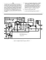
Figure 1. Complete Schematic Diagram for EM-A-10

68

220

68

b

Содержание Vickers EM-A-10

Страница 1: ...Revised 09 01 87 I 3081 S Single Ended Linear DC Servo Amplifier EM A 10 Vickers Servo Valves Service Data ...

Страница 2: ...ble 1 for electrical and mechanical specifications C Installation The EM A 10 servo amplifier is designed for mounting on a power supply plate such as the EMP A 11 Input and output connections to the amplifier circuitry are provided by printed circuit pin connections on the module These pin connections when installed into a plug in receptacle must be connected as shown in Table 2 TB2 wiring interc...

Страница 3: ... circuit Dither The dither signal 60 to 400 Hertz is connected to pin 1 of the plug in module A variable resistive divider network R16 and R18 provide adjustment of the value of the dither The dither is applied to pin two 2 of amplifier A2 through resistor R17 Dither signal is used to keep the servo flapper in constant motion thus preventing the flapper from magnetizing in a locked condition again...

Страница 4: ... 0 volts at one end of the test potentiometer adjustment range to approximately 1 5 volts at the other If the amplifier performs as indicated it is operating normally 6 Remove AC power from the system 7 Connect symbolized wiring removed in step E 2 12 11 6 5 7 4 8 3 2 1 3 8 15 7 13 1 2 5 4 6 D C Supply In R15 R13 2 2K R11 Z2 Q4 Q2 D 2 2 7K R7 1 5 K Z 4 Z 6 Z 5 Supply Out R9 1 5 K R6 Supply Out 2 7...

Страница 5: ...gram of the EM A 10 Figure 3 Simplified Schematic Diagram of the EM A 10 10 Vdc R16 22K R17 22K DITHER R18 1K R20a R20 82K 50K R1 R2 5K A1 A2 R21 3 3K 10 1 INV 4 5 R4 200K R3 10K R23 3 3K 12 15 R26 3 Ω Load 11 Factory Adjust ...

Страница 6: ...nals 4 5 Symbolize the wires removed to prevent error Common ground Input signal Test Potentiometer 5000 Ohm Linear Potentiometer Note If the EMP A 11 power supply is not used connect the power source as shown to test the EM A 11 amplifier Figure 4 Test Potentiometer Wiring Diagram 1 2 3 4 5 6 7 8 DC DC ...

Отзывы: