background image

10

Instructional Booklet 

IB022010EN

Effective July 2019
Revision #4

Instructions for installation, operation,  

and maintenance of medium voltage 

VC-W MR2 (integral racking) 

EATON

 www.eaton.com

Method 2

, applies to pendant without enable button .

On power up if both connect and disconnect positional limit 

switches are closed then the controller will look to see what series 

of I/O controls are closed . The gear type is then set depending on 

what pushbuttons are closed . The gear type can then be verified 

with the diagnostic display . Below are the sequences of closed 

contacts to set each gear type .

Closed contacts upon power-up

Gear type

Positional limit switches  

(ref 

Figure 15

)

I/O Controls jumper

01

“Disc” & “Conn”

Pin 8 to pin 1

02

“Disc” & “Conn”

Pin 8 to pin 2

03

“Disc” & “Conn”

Pin 8 to pin 3

04

“Disc” & “Conn”

Pin 8 to pin 1 and 2

05

“Disc” & “Conn”

Pin 8 to pin 2 and 3

06

“Disc” & “Conn”

Pin 8 to pin 1, 2 and 3”

07

“Disc” & “Conn”

None

15

“Disc” & “Conn”

Pin 8 to pin 1 and 3

Procedure: 
Step 1. 

- Using an Ethernet cable and a RJ485 to 8 pin terminal 

block adapter .  Connect one end of the Ethernet cable to the 

discrete I/O control connection shown on 

Figure 12

 .  Connect the 

other end of the Ethernet cable to the RJ485 connection shown on 

Figure 12

 .

Setting the Modbus address

If the enable button is present (

Figure 7

 and 

8

) the enable  button 

must be held to operate the pendant . The Modbus address of a 

controller board is set using the pendant . The available MODBUS 

addresses are 01 to 99 for one RS485 network . 

To set the MODBUS address, follow the steps below:

1 .  Connect pendant to the cell to be programmed .
2 .  Hold down the “Intermediate” button and within 3 seconds 

press and hold the “Connect” button until the 2-digit LED display 

begins to flash “##”, at the same time the “Connect” LED will 

begin to flash .

3 .  Now the “Test” and “Disconnect” buttons can be used to scroll 

up and down (01 to 99) until the desired address number is 

reached . While scrolling, the “Connect” LED will continue to 

flash to let the user know that the address is not set .

4 .  Once the desired address number is reached, press the 

“Connect” button to connect to the Modbus address displayed .

5 .  Press “Disconnect” to return to operation mode .
6 .  At this time the address can be verified using the controller 

diagnostic display described above .

The MODBUS address can be modified after being set using the 

same sequence .

ote:

N

See Instruction Booklet IB022022EN for information on the MODBUS 

interface to VCPW-MR2 and VCPW-HD controllers .
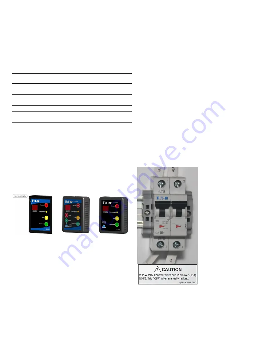
Manual racking

Follow the steps listed below to manually rack the MV device in the 

case of a motor/controller failure or loss of control power .

1. 

Turn “Off” the 15 A two-pole LV circuit breaker mounted in the  

LV compartment (see 

Figure 11

) .

a. 

This action does two things:

1. 

It ensures that the motor will not turn on during  

manual racking .

2. 

It prevents the motor from back feeding voltage  

and causing the user to apply excessive torque to  

the lead screw .

2. 

Once the LV circuit breaker is turned “Off,” the operator can 

insert the standard racking tool (for 5/15 kV 1/4 high auxiliary 

drawers, use a standard 1/2” socket) and rack the MV device to 

the connected or disconnected position .

a. 

This will require slightly more torque than normal because it 

will be driving through the motor gearbox .

In the case that the motor is jammed and the lead screw does not 

turn freely or with less than 35 ft-lbs (47 .45 N∙m) of torque, the 

operator can apply approximately 70 ft-lbs (94 .91 N∙m) of torque 

and the lead screw will break away from the motor . Once the lead 

screw has broken free from the motor, the MV device can be racked 

manually . The unit should then be inspected and a new lead screw 

installed .

Figure 11. 15 A circuit breaker.

Terminals 1 and 2 are the 120 VAC power supply .
Terminals 3 and 4 are the 140 VDC motor circuit .

Содержание VC-W MR2

Страница 1: ...Open permissive 9 Instructions for installation operation and maintenance of medium voltage VC W MR2 integral racking Description Page E6 Communication error 9 E7 No MV device 9 E8 Firmware compatibi...

Страница 2: ...2 Instructional Booklet IB022010EN Effective July 2019 Revision 4 Instructions for installation operation and maintenance of medium voltage VC W MR2 integral racking EATON www eaton com...

Страница 3: ...source governing the rights and remedies of any purchaser of this equipment is the contract between the purchaser and Eaton NO WARRANTIES EXPRESSED OR IMPLIED INCLUDING WARRANTIES OF FITNESS FOR A PA...

Страница 4: ...SC 29649 All possible contingencies which may arise during installation operation or maintenance and all details and variations of this equipment are not encompassed by these instructions If further i...

Страница 5: ...ive interlocks wired for every breaker cell with integrated racking and one for every auxiliary cell with integrated racking Breaker cell specific interlocks 1 Normally closed mechanism operated compa...

Страница 6: ...pass E5 error circuit CAUTION by jumpering terminals 51 to 54 you have defeated the inter lock circuit For troubleshooting move the black mo tor lead on terminal 47 to terminal 44 to bypass E2 error c...

Страница 7: ...the auxiliary pan assembly This lock prohibits an operator from manually inserting a crank into the Lev in assembly and manually racking the breaker or auxiliary device as specified in the switchgear...

Страница 8: ...hen motor current is in excess of allowed value Multiple causes could create this condition E1 error codes may occur if system is operated on temporary generator power Operator should shut off power t...

Страница 9: ...ibility error This state results from the pendant and controller card not having compatible firmware Contact your Eaton representative to have the firmware updated E9 No test MR2 open close only This...

Страница 10: ...Disconnect buttons can be used to scroll up and down 01 to 99 until the desired address number is reached While scrolling the Connect LED will continue to flash to let the user know that the address...

Страница 11: ...device from a distance of up to 30 ft 9 14 m from the equipment with a Cat 5 cable typically there will be an RJ 45 jack located on the front panel of the switchgear see Figure 14 The MV device can b...

Страница 12: ...cking device via a SCADA system or multiple Modbus interface communication systems These systems can be wired to a central control room or to a remote panel located a safe distance away from the equip...

Страница 13: ...ontrol power to breaker a At this time the breaker open and close operations can be tested electrically b To proceed further and rack the breaker to the connected position the breaker must be open 1 A...

Страница 14: ...ator should then open the breaker c After the breaker is open the error can be cleared by pressing the disconnect button 8 Once the error is cleared the operator can rack the breaker to the test or di...

Страница 15: ...15 Instructional Booklet IB022010EN Effective July 2019 Revision 4 Instructions for installation operation and maintenance of medium voltage VC W MR2 integral racking EATON www eaton com Notes...

Страница 16: ...16 Instructional Booklet IB022010EN Effective July 2019 Revision 4 Instructions for installation operation and maintenance of medium voltage VC W MR2 integral racking EATON www eaton com...

Страница 17: ...17 Instructional Booklet IB022010EN Effective July 2019 Revision 4 Instructions for installation operation and maintenance of medium voltage VC W MR2 integral racking EATON www eaton com...

Страница 18: ...n USA Publication No IB022010EN TBG001320 July 2019 Eaton is a registered trademark All other trademarks are property of their respective owners Instructions for installation operation and maintenance...

Отзывы: