background image

17

Instruction Booklet 

IB02201004E

Effective October 2017 

Revision #4

Instructions for installation, operation, and 

maintenance of 38 kV type VacClad-W, 

150 BIL switchgear indoor housings 

EATON

 www.eaton.com

Section 7: Lubrication

VacClad-W switchgear is designed so that lubrication is not required 

under normal conditions .  However, abnormal local conditions such 

as high humidity, salt-laden atmosphere, corrosive gases, or severe 

circuit operating conditions may demand the use of lubricants .  All 

mechanical parts have been lubricated during assembly with molyb-

denum disulphide grease (Eaton Material No .  53701QB) .  The appli-

cation of the lubricants should be held to a minimum to reduce the 

accumulation of dust and dirt .

7.1 Where to lubricate

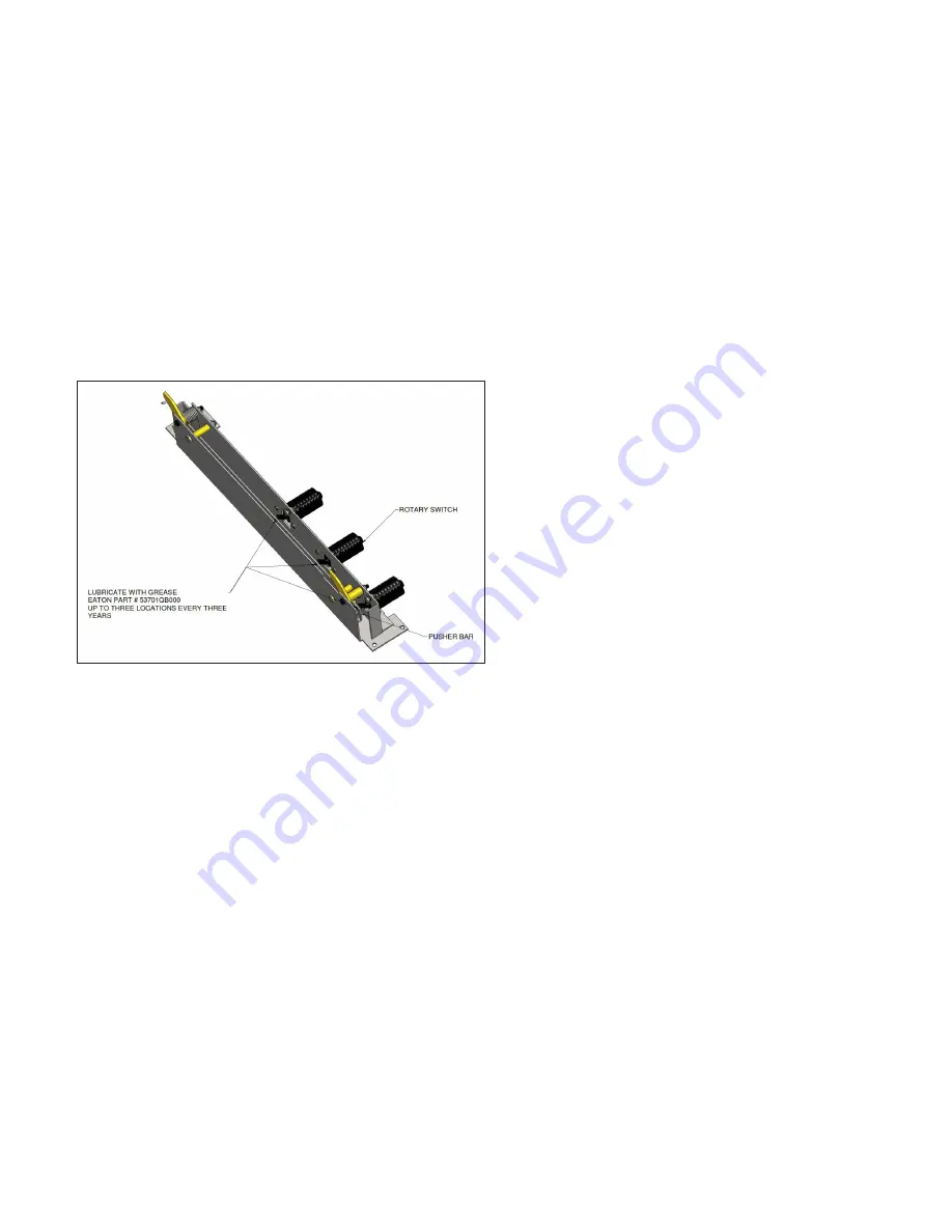
1 .  MOC switch (refer to #9 in Figure 15) – Grease (Eaton Electrical 

Material No .  53701QB) should be applied to the three locations 

where the rotary switch assemblies link to the Push Bar assem-

bly (see Figure 16) .  This should be done at least every three 

years .

Figure 16. Lubrication Locations for the MOC Switch.

Section 8: Renewal parts

When ordering renewal or spare parts, include as much information 

as possible .  In many cases, the style number of the new part can 

be obtained from identification on the old part .  Always include a 

description of the part .  Specify the rating, structure number, and 

shop order number of the switchgear housing in which the part is  

to be used .

Содержание VacClad-W

Страница 1: ...Operation of the system 14 Inspection and maintenance 15 Lubrication 17 Renewal parts 17 Accessories 18 Metal clad switchgear field taping procedure 38 kV 23 Instructions for installation operation and maintenance of 38 kV type VacClad W 150 BIL switchgear indoor housings Instruction Booklet IB02201004E Effective October 2017 Revision 4 ...

Страница 2: ...2 Instruction Booklet IB02201004E Effective October 2017 Revision 4 Instructions for installation operation and maintenance of 38 kV type VacClad W 150 BIL switchgear indoor housings EATON www eaton com ...

Страница 3: ...t The sole source governing the rights and remedies of any purchaser of this equipment is the contract between the purchaser and Eaton NO WARRANTIES EXPRESSED OR IMPLIED INCLUDING WARRANTIES OF FITNESS FOR A PARTICULAR PURPOSE OR MERCHANTABILITY OR WARRANTIES ARISING FROM THE COURSE OF DEALING OR USAGE OF TRADE ARE MADE REGARDING THE INFORMATION RECOMMENDATIONS AND DESCRIPTIONS CONTAINED HEREIN In...

Страница 4: ...tion Eaton s VacClad W 38 kV 150 BIL switchgear indoor housing assem bly provides centralized control and protection of medium voltage power equipment and circuits in industrial commercial and util ity installations involving generators motors and feeder circuits Several built in interlocks and safety features are provided The construction of the VacClad W 38 kV 150 BIL switchgear pro vides the en...

Страница 5: ...hardware is in place and torqued per Section 2 3 Table 3 8 Confirm that no tools or objects are left inside the enclosure 9 Confirm that all devices covers doors panels and so on are in place 10 Before start up perform a field power frequency withstand Hi Pot test using test voltages given in Table 1 Table 1 Power Frequency Withstand Test Voltages Rated Maximum Voltage kV Power Frequency Withstand...

Страница 6: ...on Bronze 5 6 78 10 13 56 15 20 34 40 54 24 55 74 58 Figure 1 Tie bolt Locations 31 33 1 2 3 4 5 6 7 8 9 12 13 10 17 16 32 33 15 14 31 24 25 22 23 20 21 19 18 26 27 28 29 30 B Remove the rear covers or open the rear doors if applicable of the cells on the sides of all the shipping split Remove from these sections the angled metal barrier and vertical main bus barrier from the cable compartment in ...

Страница 7: ...tations and larger substations the ground resistance should be 1 ohm or less For industrial plants and small substations the ground should be less than 5 ohms the NEC states that the ground resistance should never exceed 25 ohms Ground Link Step 5 Connect the high voltage bus between the shipping sections A Remove the rear covers or open the rear doors if applicable of any remaining cells that wer...

Страница 8: ...necting the cables to them Use the flexible connectors to connect the arial lugs to the conductors This will keep strain off the insulators of the pothead or the terminator Tape or otherwise insulate the entire joint including the flexible connectors see the Metal clad switchgear field taping procedure 38 kV section in this manual G If zero sequence transformers are used pass the power cables thro...

Страница 9: ... removal of the drawers from the units prior to performing the following actions After removing the drawers check for any damage to the transformers transformer fuses and fuse tubes drawers and cell parts Figure 6 Auxiliary Compartment with Front Cover Installed Cover Interlock Bracket Cover Guide Racking Cover Plate Viewing Window Cover Guide Perimeter Bolting Cover Guide Figure 7 Auxiliary Compa...

Страница 10: ...onnect position Use the lighting out or ringing methods to verify 3 Verify that the primary shutters are open and have operated properly The shutters can be viewed from within the closed compartment through the viewing window on the front cover 4 The front cover can not be removed when a transformer drawer is in the Connect position The transformer drawer must be in the Disconnect position to remo...

Страница 11: ...BODILY INJURY AND PROPERTY DAMAGE Figure 10 Breaker Compartment with Shutters Closed Safety Shutters Lock Closed Bracket Figure 11 Breaker Compartment with Shutters Latched Open 3 Ring type current transformers The ring type current transformers are mounted so they slip over the primary disconnecting contact insulating high voltage termi nals at the rear wall of the breaker compartment There is sp...

Страница 12: ...ly withdrawn position 2 Move the LOTO slider to the left in order for the LOTO slider to engage the slider used for racking Refer to 6 in Figure 15 3 Insert a LOTO option see Figure 14 into the circuit breaker pan LOTO provisions see Figure 13 4 When it is safe to do so remove the lock to allow the LOTO slider to move to the right when racking the break er is required Figure 13 Lockout Tagout Prov...

Страница 13: ...es when the breaker is in the fully connected position Represents positive indication of the breaker in the Connect posi tion by use of a red flag that rotates into viewing position when the breaker is fully connected 8 Slider interlocks prevent removing a closed breaker 9 The mechanism operated cell MOC switch is an assembly of switches that is operated by a lever on the breaker mechanism Refer t...

Страница 14: ...stallation or test handle them carefully Replace the covers as soon as possible to keep dust and dirt out of the components Step 6 Perform a loading check of the control circuits Before energizing the control circuits check the control bus with an ohmmeter to make sure there are no short circuits in the control wiring If an ohmmeter is not available connect a small fuse in series with the source o...

Страница 15: ...eplacing fuses 1 Follow the instructions in the Installation procedure section of this manual to remove the transformer drawer from the auxiliary compartment With the transformer s removed from the unit unscrew the contact spring retaining screws 2 located at the end of the fuse tube Remove the fuse from the tube and replace with a new fuse Reinstall the contact spring on the new fuse and install ...

Страница 16: ...ections and test are recommended in the battery supplier s instructions At the same time the battery is checked inspect the battery charger and remove accumulations of dust and dirt On all chargers having a manual transfer switch for setting the charging rate check carefully to be sure that the selector switch is returned to the value appropriate for a floating charge at the end of the periodic in...

Страница 17: ...o 53701QB The appli cation of the lubricants should be held to a minimum to reduce the accumulation of dust and dirt 7 1 Where to lubricate 1 MOC switch refer to 9 in Figure 15 Grease Eaton Electrical Material No 53701QB should be applied to the three locations where the rotary switch assemblies link to the Push Bar assem bly see Figure 16 This should be done at least every three years Figure 16 L...

Страница 18: ...t jumper is used for electrically operating the circuit breaker outside its compartment 9 2 Optional accessories 9 2 1Test cabinet A test cabinet is used for electrically opening and closing of the breaker when it is outside its housing The cabinet includes termi nals for control power connections a set of pull out fuse blocks for control power disconnect necessary control equipment and a cable ha...

Страница 19: ...y to oper ate the lifter and transformer pan with a transformer drawer A Securing the lifter pan to the lifter 1 Expand the lifter base legs so they span the lifter pan To do this unscrew and remove the adjustment bolts and pull each leg outward until the third hole in each leg is in line with each mating through hole This exposes two of the three leg holes as shown in Figure 22 Screw the bolts ba...

Страница 20: ... tion of the drawer is butted up against the lower section of the drawer see Figure 9 3 Roll the drawer onto the lifter pan and up against the rubber stops Use the pan rails as a guide see Figure 27 NOTICE DO NOT HANDLE THE FUSE TUBES AND MATING PARTS WHILE MOVING THE TRANSFORMER DRAWER THIS MAY CAUSE DAMAGE TO THESE PARTS Figure 25 Break Pedal for Locking the Lifter 4 Make sure the drawer safety ...

Страница 21: ... The guide stops butt up against the switchgear side sheets and prevent the lifter from moving too far into the compart ment As the pan is moved into place pan safety latches bias off the switchgear side sheets and latch to the side sheet flanges when the pan is fully in place These safety latches along with the lifter brake prevent the lifter and pan from backing out of the compartment when the d...

Страница 22: ...awer from the cell 7 Pull the drawer using the red release lever onto the lifter pan making sure that the wheels on the drawer roll on the pan between the pan rails Pull the drawer all the way back on the pan and up against the rubber stops NOTICE DO NOT HANDLE THE FUSE TUBES AND MATING PARTS WHILE MOVING THE TRANSFORMER DRAWER THIS MAY CAUSE DAMAGE TO THESE PARTS 8 Make sure the drawer safety lat...

Страница 23: ...igh voltage EPR insulating tape Trade name Scotch 130C 10 2 Using an insulating boot Step 1 Clean the area of dirt and foreign matter Use a clean dry cloth or if necessary dampen slightly with distilled water Do not use any abrasives or solvents Step 2 Place the boot over the joint so it fits in place Fasten together with plastic wire ties Cut off excess ends of plas tic wire ties 10 3 Cable termi...

Страница 24: ...LUDES A BAND OF TAPE CONSISTING OF ONE OR MORE TURNS WRAPPED DIRECTLY ON TOP OF EACH OTHER LAYER INSULATING TAPE 1 INCH WIDE WRAPPED FROM ONE END OF THE JOINT TO THE OTHER OR TO A PAD SO EACH SUCCEEDING TURN LAPS THE PREVIOUS TURN BY THE AMOUNT SPECIFIED IN THE CHART OVERLAP A SPECIFIED DISTANCE MEASURED ALONG THE PRE INSULATION STARTING FROM THE POINT WHERE THE PRE INSULATION ENDS AND THE EXPOSED...

Страница 25: ...ections must be made DWG NO MODEL REV SHEET OF TITLE ALL REV NOTES LISTED ON SHT 1 REV MODEL FILENAME T BLK REV 4 C 7819C90 2 2 4 JOINT TAPING THRU JOINTS WITH HARDWARE 1 CLEAN AREA OF DIRT AND FOREIGN MATTER 2 WIPE PREINSULATION WITH ISOPROPYL ALCOHOL 3 APPLY FILLER OVER BARE CONDUCTOR AND HARDWARE TO COVER AND SMOOTH OUT THE SURFACE BLEND CONTOUR INTO PRE INSULATION SURFACES TRY TO PREVENT AIR P...

Страница 26: ...ransformers Insulated pothead bushing Pothead ground lead must be carried through the Zero Sequence current transformer and solidly grounded on the load side of the ct as shown Use 6 wire with 600V insulation Power Cables Conduit when used Cable connections to switchgear terminals when used with Insulated Pothead Conduit must be terminated and solidly grounded on the load side of the current trans...

Страница 27: ...struction Booklet IB02201004E Effective October 2017 Revision 4 Instructions for installation operation and maintenance of 38 kV type VacClad W 150 BIL switchgear indoor housings EATON www eaton com Notes N ...

Страница 28: ...ved Printed in USA Publication No IB02201004E TBG001315 October 2017 Eaton is a registered trademark All other trademarks are property of their respective owners Instructions for installation operation and maintenance of 38 kV type VacClad W 150 BIL switchgear indoor housings Instruction Booklet IB02201004E Effective October 2017 Revision 4 ...

Отзывы: