


5
Instruction Booklet
IB158007EN
Effective September 2016
Installation instructions for Eaton SPC series
surge protective device (SPD)
EATON
www.eaton.com
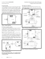
4.5 Optional flush mount plate
Optional Flush Mount Plates are available for both the P1 and P2
enclosure sizes . See
Figures 6 & 7.
Catalog# FLUSHMNTPLATE13
– P1 Enclosure Flush Mount Plate
Catalog# FLUSHMNTPLATE14
– P2 Enclosure Flush Mount Plate
Figure 6. Optional P1 Enclosure Flush Mount Plate. Catalog#
FLUSHMNTPLATE13.
Figure 7. Optional P2 Enclosure Flush Mount Plate. Catalog#
FLUSHMNTPLATE14.
4.6 Wiring installation
WARNING
IMPROPER WIRING COULD CAUSE DEATH, INJURY AND/OR EQUIPMENT
DAMAGE. ONLY LICENSED/QUALIFIED ELECTRICIANS WHO ARE TRAINED
IN THE INSTALLATION AND SERVICE OF ELECTRICAL SERVICES ARE TO
INSTALL AND SERVICE THIS EQUIPMENT.
TO MAXIMIZE THE SPD’S PERFORMANCE, TWIST AND BIND THE WIRES
TOGETHER TO REDUCE THE IMPEDANCE OF THE WIRE.
ARC FLASH DURING INSTALLATION COULD CAUSE INJURY OR DEATH.
USE APPROPRIATE SAFETY PRECAUTIONS AND EQUIPMENT FOR ARC
FLASH PROTECTION.
Locate the electrical system’s applicable wiring schematic in
Section
5 Wiring Diagrams.
Turn OFF
power to the electrical equipment being connected to the
SPC
in accordance with NEC, CEC, state, county and local codes
for all safety ratings.
Eaton SPC’s covered in this guide are designed with internal overcur-
rent protection and do not require an external overcurrent protection
device (OCPD) unless otherwise required by NEC, UL, and local
electrical requirements to protect electrical conductors . NEC Article
310 .15 (B) (16) defines the maximum rating of the OCPD required to
protect the electrical conductors .
NEC shows #10 AWG conductors at 60°C typically requiring a 1-pole
(for single phase systems), 2-pole (for split-phase systems) or 3 pole
(for 3-phase systems) 30A branch circuit breaker to protect SPC con-
ductors .
Twist and bind the wires of the SPC unit tightly together . Minimize
overall lead length to optimize SPC performance . For wire lengths
longer than four inches, phase wires should be twisted once for
each four inches of wire length to maximize performance .
otee:
N
to maximize the SPC’s performance, 10 AWG wire length should be
less than 14” (35cm) twisted and bound together .
If remote monitoring is required, connect the Form C relay contact
wiring to an alarm or building monitoring system . These relay con-
tacts are rated:
2A at 30Vdc or 250Vac
Refer to
Table 2 – SPC Series Form C Wire Color Codes for color
codes
of relay wires (shown in the energized state) .
otee:
N
Utilization of Form C contacts is optional . Connection of Form C wires
is not required for the proper operation of the SPC .
Tighten and recheck all connections and mounting .
Table 2. SPC Series Form C Wire Color Code
FORM C WIRE COLOR CODE
CONTACT
COLOR
COM
BLUE/WHITE
NO
RED/WHITE
NC
ORANGE/WHITE