


12
PA/GA Power Management unit
SONIX Pm10 TECHNICAL mANUAL
TM365-1 / A June 2022 www.eaton.com
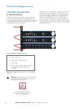
5 Setup and Configuration
Sonix Pm10 unit does not have any external switches
nor jumper links to set.
All units come pre-configured with a general setup
to support a secondary input but prefer primary. If a
different configuration is required, please contact your
local Eaton representative.
6 Unit operation
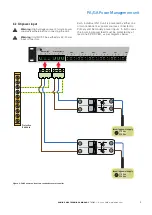
6.1 Power loss protection
When the Sonix Pm10 unit detects an AC power loss
on the active input, it will immediately begin swapping
all the outputs to use a redundant AC input, if available.
When a preferred input becomes available again, the
unit will wait for at least 10 seconds before swapping
back. This delay is intended to allow the input to
stabilise, to avoid switching during surges from other
loads and to ensure the supply will remain available and
will not immediately fail again.
ote:
N
There will be a finite gap in supply power while the unit is
carefully switching inputs, this is to ensure that the two supplies are
not connected together.
ote:
N
Output voltage is dependent on which input is currently selected.
All outputs will have the same source.
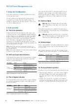
6.3 AC Power input status indication
Pm10 reports the status of its AC power inputs via pairs
of green and red LEDs grouped with each input (see
Figure 1), as per table below:
LED Name
State
Status
Primary /
Secondary Input
Green
Input healthy and in use
Flashing Green
Input healthy and on standby
Red
Input missing (in fault)
Green + Flashing Red Input healthy but with previous
input fault
Table 4. Front panel power input status indicators.
6.3 Power Outputs indication
Pm10 reports the status of its outputs via pairs of green
and red LEDs grouped with each output (see Figure 1),
as per table below:
LED Name
Green
Red
Status
Output 1 – 8,
Aux Output
On
Off
Output healthy
Off
On
Output missing or fuse failure
On
Slow flashing Healthy but with previous fuse
fault
Table 5. Front panel power outputs status indicators.
Fuse monitoring for Pm10’s individual outputs can be
disabled in the configuration via SAS (please refer to
SAS Product Manual for details). The unit will still be
protected, but the status of the output(s) will not be
reported.
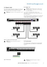
6.4 Auxiliary Output
Warning:
High voltages present. Power down
Pm10 unit before connecting or disconnecting
this output.
This output is available as a reliable AC power source
for other equipment in the PA/GA rack, for example fans
and air conditioning.
Warning:
Observe load limit of 4 A on unit and
avoid connecting items with high inductive loads.
These typically have high surge currents.
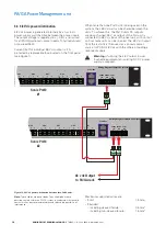
6.5 DC Rack Output
This is a regulated 48 V dc output, dedicated as a power
source for other Sonix units that are dc powered, such
as Hmi or Vw2.
Pm10 reports the status of its DC Rack Output via pair
of green and red LEDs (see Figure 1), as per table below:
LED Name
Green
Red
Status
Rack DC
On
Off
Output healthy
Off
On
Output missing or fuse failure
On
Slow flashing Healthy but with previous fuse
fault
Table 6. Front panel dc rack output status indicators.
6.6 Front panel button operation
The Sonix Pm10’s front panel button has three functions:
1. Selecting measurements – each short press toggles
between Voltage and Current measurements and
presents the result on the front panel display (see
Figure 1).
2 Initiate local fault reset – long-press of the button
will reset all fault flags on the unit. If the fault is still
present, it will get reintroduced after few seconds.


