11
Sonix Pbx Technical Manual
SONIX PBX TECHNICAL MANUAL
TM372 / A June 2022 www.eaton.com
Message monitoring and abort connections
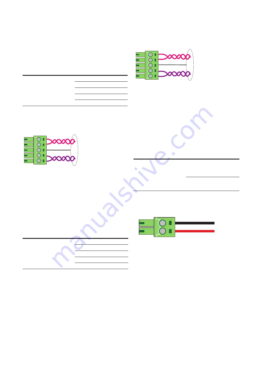
A 5-way connector provides the interface to local
loudspeaker for listening to the message being recorded
and for a push button to prevent the message from
broadcasting if required.
Cable Specification
Type
Description
Label
2off Twisted pair, individual and
overall screen.
0.25 mm² to 0.5 mm² (ferrules with
sleeve)
0.25 mm² to 1.5 mm² (ferrules
without sleeve)
Output
Audio output
A1
Output
Audio output
A2
---
Screen
SCN
Input
Keyline 1
COM
Input
Keyline 2
N/C
Table 5 – Message monitoring interface description
Typical wiring connections
Figure 4 – Message monitoring and abort
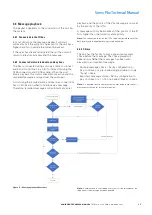
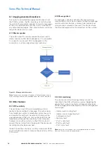
3.3.3 Isolated audio and key line connections
Two 5-way connectors provide a duplicated interface for
isolated audio and control lines for connection to other
third party equipment operating alongside the RJ45
connections. These interfaces can be used to replace
the RJ45 connections provided they are connected to
an IO Tu unit’s audio input, usually when installed in a
separate cabinet with PABx equipment.
Cable Specification
Type
Description
Label
2off Twisted pair, individual and
overall screen.
0.25 mm² to 0.5 mm² (ferrules with
sleeve)
0.25 mm² to 1.5 mm² (ferrules
without sleeve)
Output
Audio output
A1
Output
Audio output
A2
---
Screen
SCN
Output
Keyline 1
K1
Output
Keyline 2
K2
Table 6 – Audio & Key line interface description
Typical wiring connections (A-side & B-side
)
Figure 5 – Isolated audio and Keyline outputs
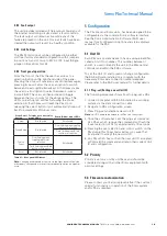
3.3.4 Power connections
The Sonix Pbx is powered via a 2-core 48 V dc input
on the rear of the unit. This input should be connected
to the managed 48 V dc power output from the Sonix
PM10 power management unit.
Note: As these cables are power feeds they should
be routed within the PA/GA system in a way so as to
avoid contact with signal or audio cables and other high
voltage cables.
Cable Specification
Type
Description
Label
2off Twisted pair, individual and
overall screen.
0.25 mm² to 0.5 mm² (ferrules with
sleeve)
0.25 mm² to 1.5 mm² (ferrules
without sleeve)
Input
+48Vdc
+
Input
0Vdc
-
Table 7 – Power interface description
DC Power connection
Figure 6 – Power connections
3.3.5 General fault output connections
The general fault output is a low voltage, volt free
contact output. The output can be set in configuration
to either normally open or normally closed. It is
recommended that the output is set to normally closed
so a loss of power to the unit will be detected.
R
Sonix Pbx
TM
LOCAL STATUS
POWER SUPPLY
OPERATIONAL
Fuse
Cancel
Zoned / Global
Source Select
Reset
DC PSU
2w
E+M
2w
Global
Message
Zoned
Message
Message
Cancel
Monitor
Active
Pbx
playback
Pbx
record
Power
8
7
6
5
4
3
2
1
Pbx I/P
MONITOR
A SIDE O/P
B SIDE O/P
48V
DC
I/P
+ -
Fault
O/P
N/C
Com
K1 K2 SCN A1 A2
I/O Bus A
I/O Bus B
A1 A2 SCN COM N/C
A1 A2 SCN K1 K2
A1 A2 SCN K1 K2
COMPLIANT
7
6
5
4
3
2
1
2-Wire connection
Screen
E&M connection (optional)
Push button connection
Screen
Loudspeaker connection
Keyline connection
Screen
Audio connection
Power connection
0Vdc (-)
48Vdc (+)
General fault connection
N/C
Com
Pbx I/P
Primary Unit ID 1
Secondary Unit ID 2+
2 wire
Telephone I/F
Pbx I/P
K1 K2 SCN A1 A2
K1 K2 SCN A1 A2


