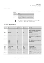
5 Parameters
5.3 “Extended” parameter group
DB1 Variable Frequency Drives
09/17 MN040034EN
www.eaton.com
35
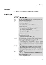
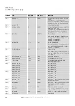
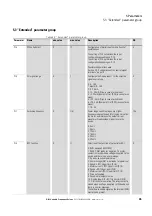
5.3 “Extended” parameter group
Table 22: “Extended” parameter group
Parameter
Name
min. value
max. value
Description
DS
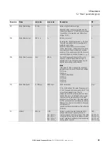
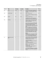
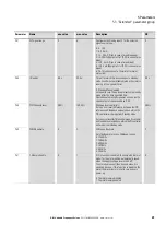
P-15
DI Config Select
0
17
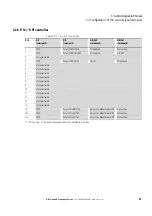
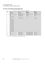
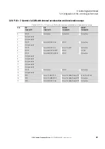
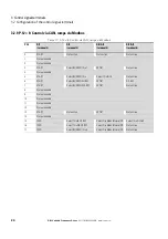
Configuration of digital inputs with a fix set of
combinations
The setting of P-15 determines the input
configuration depending on P-12.
The setting of P-15 determines the input
configuration depending on P-12.
Possible con
fi
gurations
→
Section 3.2 “Configuration of the control signal
terminals“, page 16
5
P-16
AI1 signal range
0
7
Configures the Analog input 1 for the selected
signal source type.
0: 0 - 10V
1: bipolar 0 - 10V
2: 0 - 20 mA
3: t 4 - 20 mA (Trips in case of wire break)
4: r 4 -20 mA (Ramps to f-fix1 (P-20) in case of wire
break)
5: t 20 - 4 mA (Trips in case of wire break)
6: r 20 - 4 mA (Ramps to f-fix1 (P-20) in case of wire
break)
7: 10 - 0V
0
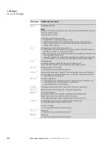
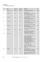
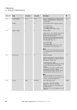
P-17
Switching frequency
0
f (I
e
)
Power stage switching frequency. Higher
frequency reduces the audible 'ringing' noise from
the motor, and improves the output current
waveform, Disadvantage: Higher loss in the
device.
0: 4 kHz
1: 8 kHz
2: 12 kHz
3: 16 kHz
4: 24 kHz
5: 32 kHz
f (I
e
)
P-18
RO1 Function
0
11
Selection of the function of output relay RO1
0: RUN, approved (FWD/REV)
1: READY, DB1 ready for operation. The relay
contact is closed when a voltage is applied to the
device and there is no error message.
2 : Speed = speed setpoint value
3: Error message (DB1 is not ready for operation)
4: Speed
≧
RO1 Upper Limit (P-19)
5: Motor current
≧
RO1 Upper Limit (P-19)
6: Speed < RO1 Upper Limit (P-19)
7: Motor current < RO1 Upper Limit (P-19)
8: Drive not enabled
9: Speed not at setpoint value
10 : Analog input AI2 > RO1 Upper Limit (P-19)
11 : DB1 ready for operation. The relay contact is
closed when a voltage is applied to the device and
there is no error message.
The hardware enable signal on the terminal (ENA)
must also be present.
0

