


2 Installation
2.3 COM Port
CANopen for DA1, DC1, DE11
09/16 MN040019EN
www.eaton.com
13
2.3 COM Port
The electrical connection between the master and the slave(s) is established
with RJ45 cables. If multiple slaves are being used, they are connected in
parallel by using RJ45 cables and DX-SPL-RJ45-2SL1PL splitters. Please note
that the stub lines should be as short as possible.
The built-in RJ45 interface supports the CANopen protocol, making it
possible to establish a direct network connection without the need for an
additional interface module. A bus termination resistor with a resistance of
120
Ω
needs to be connected at each physical end (last module) of the
network cable in order to prevent signal reflections and the associated
transfer errors.
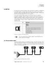
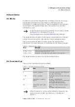
Figure 5: Configuration of the RJ45 interface
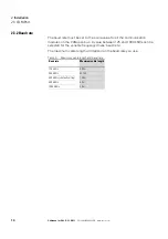
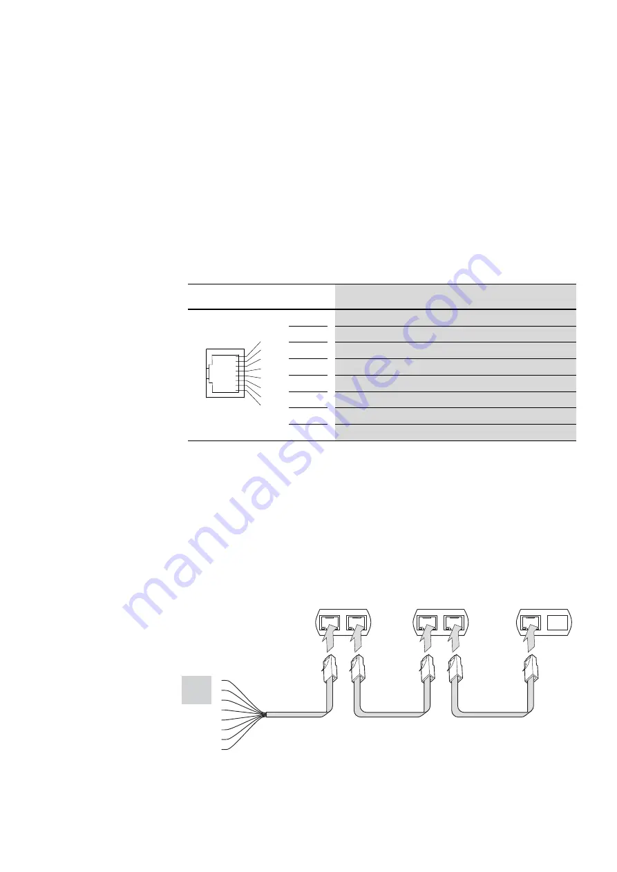
2.3.1 Bus termination resistor
The first and last modules on a CANopen network must be terminated with a
120
Ω
bus termination resistor. This resistor needs to be connected between
CAN_L and CAN_H. To do this, you can plug the EASY-NT-R bus termination
resistor into the last splitter
②
.
Figure 6: Example of a CANopen network layout
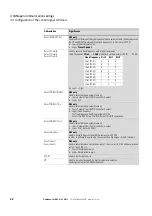
Pin
Significance
1
CANopen -
2
C
3
0 V
4
RJ45 connection / external operating unit / PC connection -
5
RJ45 connection / external operating unit / PC conn
6
24 V DC power supply
7
RS485- Modbus RTU (A)
8
RS485+ Modbus RTU (B)
→
If you are using an easy network, keep in mind that CAN- and
CAN+ need to be swapped.
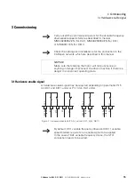
1
2
3
4
5
6
7
8
1
2
CAN_L
CAN_H
0 V 3
4
5
6
7
8
①
①
②