Introduction
Page 3
Note 1:
Each partition has one part set within it.
Note 2:
A 2-way radio keypad (KEY-RKPZ) requires a KEY-RKBS base station wired to
the control unit. Up to two radio keypads can connect to the same base station, but this
feature cannot be used to increase the total number of wired and 2-way radio keypads
beyond the limit shown in Table 1.
Note 3:
The maximum number of 1-way radio keypads (i-rk01) is in addition to the
maximum number of wired and 2-way radio keypads.
Note 4:
The maximum number of external radio siren/strobe units is in addition to the
maximum number of internal radio sounders.
Note 5:
The system-wide maximum number of outputs includes on-board radio outputs,
on-board relay and transistor outputs and outputs provided by expanders, keypads and
other peripherals. It does not include plug-by outputs.
Note 6:
The maximum number of on-board zones is for Fully-Supervised Loop (FSL) or
2-wire Closed Circuit (CC) wiring. If 4-wire CC wiring is used, the maximum number of
on-board zones is halved, unless an optional ADP-10CC board is fitted.
System architecture and supported peripherals
This section provides an introduction to the architecture of i-on intrusion systems and the
peripheral devices supported.
Note:
Please refer to the device installation instructions for electrical specifications.
System bus
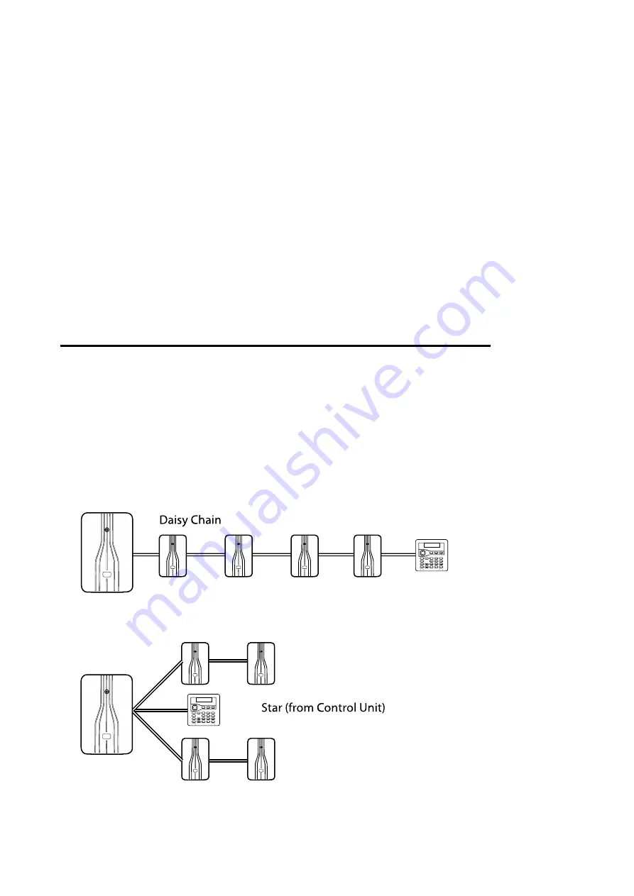
Each control unit includes connections for a four-wire RS485 bus, which is used to connect
devices such as wired keypads, expanders, remote power supplies and base stations (for
2-way radio keypads). Devices can connect to the bus using a "daisy chain" or star layout,
as shown in Figure 1.
Figure 1. Daisy Chain and Star Connections


