background image

Connection setup PC – EC4-200

10/10 MN05003003Z-EN

64

Changing the communication parameters (baud rate) of 
the CPU

X

Open the PLC configuration.

X

Click the Communication tab.

X

In the Baud rate list box select the baud rate (e.g. 57600 Bit/s 
as shown in figure 74).

X

Log on to the PLC.

The following prompt appears:

X

Click Yes.

The program is loaded. After a delay of approx. 2 minutes a 
communication fault message will be output since the baud rate 
of the CPU and the PC no longer match:

X

Acknowledge the message with OK.

In order to reconnect to the PC you must adjust the baud rate of 
the PC again to that of the project.

Connection setup via Ethernet

After you have connected the PC to the PLC with an Ethernet 
cable, select the TCP/IP communication channel in the 
programming software and enter the IP address of the PLC.
The PLC has the default address 192.168.119.60.

Selecting communication channel and address

X

Access the menu with ‹Online 

l

 Communication parameters›.

X

Push the “New…” button.

X

Select the overview of the communication channel TCP/IP 
(Level2Route) and change the name “local”e.g. to
“Ethernet-Test”

X

Confirm with OK.

X

Perform a double click on the “localhost” field and enter the 
default address 192.168.119.60

X

Confirm your details, by first pressing on another field and then 
on OK.

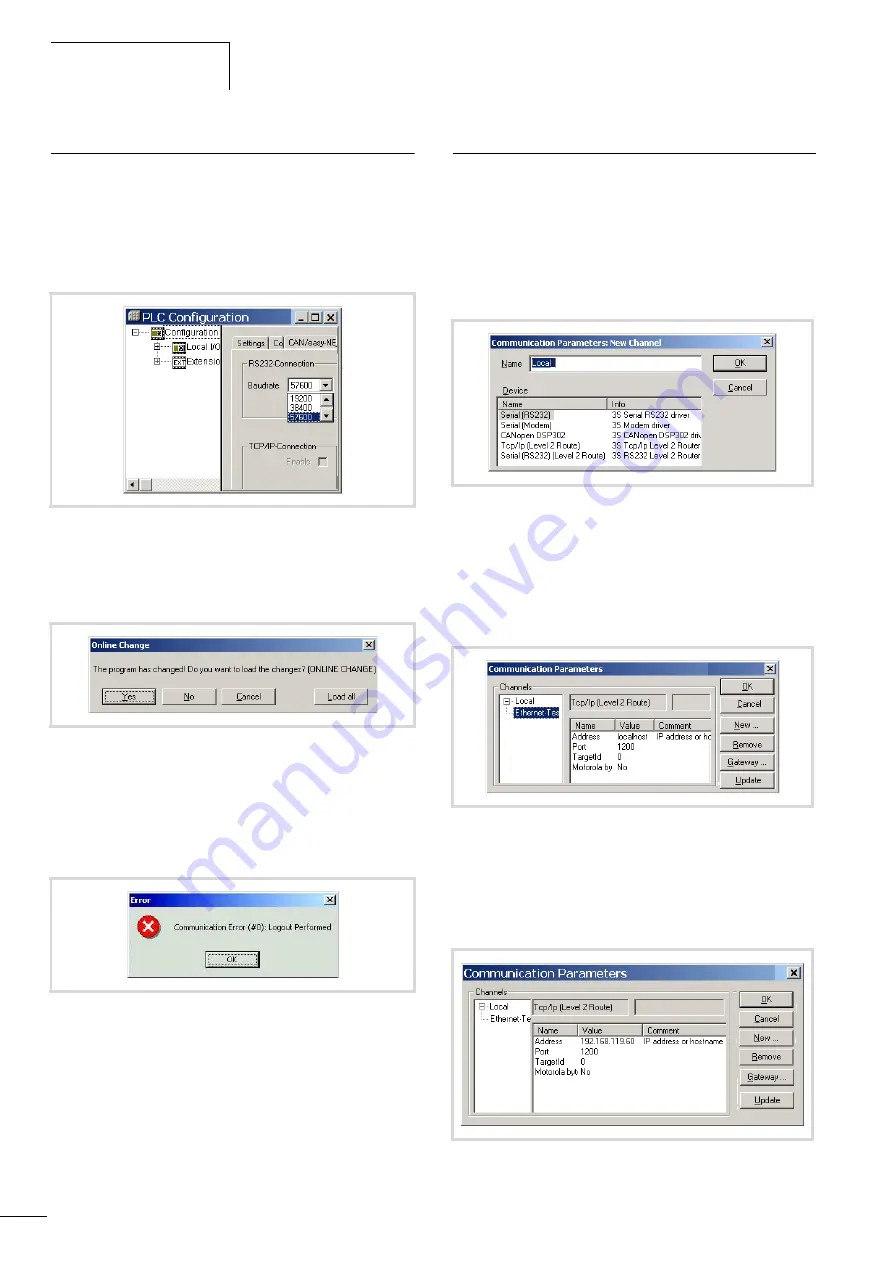
Figure 74: Specifying the CPU’s communication settings

Figure 75: Confirmation request after program change

Figure 76: Communication fault

Figure 77: Channel selection

Figure 78: Enter the IP address

Figure 79: Communication parameters with IP address

Содержание easyControl EC4-200

Страница 1: ...10 10 MN05003003Z EN replaces 01 08 AWB2724 1584GB User Manual Programmable Logic Controller easyControl EC4 200...

Страница 2: ...those in German language are translations of the original German manual 1st edition 2006 edition date 09 06 2nd edition 12 06 3rd edition 03 07 4th edition 01 08 5th edition 10 10 See revision protoco...

Страница 3: ...s Ensure a reliable electrical isolation of the low voltage for the 24 volt supply Only use power supply units complying with IEC 60364 4 41 VDE 0100 Part 410 or HD 384 4 41 S2 Deviations of the mains...

Страница 4: ...II...

Страница 5: ...units 17 Inputs 17 Diagnostics inputs 17 Outputs 17 4 Mounting 19 Mounting on top hat rail 19 Mounting on mounting plate 19 5 Installation 21 Connecting the power supply 21 Connecting digital inputs 2...

Страница 6: ...rtup behaviour 37 Setting LCD contrast and backlight 38 8 Configuration of the inputs outputs I O 39 Representation of the inputs outputs in the configuration 39 Displaying the local inputs outputs 39...

Страница 7: ...Generating and transferring a boot project 55 Storing a boot project on a memory card 55 Boot project and operating system OS on memory card 55 Erase boot project 55 Download update operating system 5...

Страница 8: ...r routing 72 15 RS232 interface in Transparent mode 73 16 Interactive display 75 Display form 75 Switching between Status display and Entry output mode 75 Function function block overview 76 Descripti...

Страница 9: ...Dimensions and weight 95 Technical data 96 Transistor outputs 101 Analog output 103 Character sets 104 Index 107 h The previous Chapter 17 The easyNet network and Chapter 18 Programming via easyNet ro...

Страница 10: ...10 10 MN05003003Z EN 6...

Страница 11: ...of CAN stations AN2700K27GB PDF To be found in Windows start menu under Programs l Moeller Software l easy Soft CoDeSys l Application examples MN05010001Z EN previously AWB2786 1554GB Library descrip...

Страница 12: ...ll find the Chapter heading at the top of right hand pages the current Section heading exceptions are the first pages of Chapters and empty pages at the end of Chapters h Draws your attention to inter...

Страница 13: ...ftware should be installed on a standard PC with the Windows NT 2000 or XP operating system Further information on the software is provided in the manual for the programming software MN05010003Z EN pr...

Страница 14: ...10 10 MN05003003Z EN 10...

Страница 15: ...ever several functions cannot be used at the same time Figure 1 Front of the EC4P 221 MRAD1 Legend a figure 2 Figure 2 Front of the EC4P 221 MTAD1 a 24 V DC power supply b Inputs c Interface for conne...

Страница 16: ...inputs I13 I14 I15 I16 provide you with additional information The inputs can be scanned in the program with symbolic operands Inputs for high speed counters You can choose between several different...

Страница 17: ...can I15 I16 in the program In the event of a short circuit set the outputs to 0 in order to prevent the thermal overload of the output circuit Data Transfer method Boot project Browser command copypro...

Страница 18: ...signment of the RS232 and Ethernet connector socket of the cable splitter corresponds with the pin assignment of the programming interface as shown in table 5 See also a section CAN easyNet PC connect...

Страница 19: ...ibrary EC_SysLibCom lib a Programming interface for connection to a PC b Multi function interface c Programming cable e g EU4A RJ45 CAB1 d Adapter with memory card or cable connection Cable connection...

Страница 20: ...ce in compliance with the CIA specification DS301V4 0 The PLC can be operated both as an NMT master as well as a CAN device on CAN networks When used as a CAN device the PLC requires an address Node I...

Страница 21: ...utputs Table 8 Number of outputs and symbolic operands The transistor outputs are provided with a short circuit monitoring function In the event that a short circuit occurs at one of the outputs this...

Страница 22: ...10 10 MN05003003Z EN 18...

Страница 23: ...the upper lip of the top hat rail Press down lightly on both the device and the top hat rail until the unit snaps over the lower edge of the top hat rail The spring mechanism should ensure that the d...

Страница 24: ...N05003003Z EN 20 Figure 13 Screw fixing the devices a Fixing brackets a a a a Figure 14 Connecting the expansion unit network module to the EC4 200 4 5 3 2 1 6 EC4 200 EASY LINK DS EASY200 EASY EASY20...

Страница 25: ...rth the conductor on one side X Don t lay the signal conductor parallel to the power conductor X Connect inductive loads that you are switching via the outputs to a separate power supply or use a supp...

Страница 26: ...for the setpoint potentiometer and various sensors shown in the examples with the 0 V of the power supply Figure 17 Setpoint potentiometer Figure 18 Setpoint potentiometer with upstream resistor Figur...

Страница 27: ...sends pulses to input I1 An internal counter processes the pulses You can choose between a 16 bit counter max 65535 and 32 bit counter max 4294967295 The pulse transmitter for the 32 bit counter must...

Страница 28: ...Unlike the inputs you can connect the EC4P 221 222 MR EASY6 RE relay outputs to different phase conductors Figure 24 Relay outputs EC4P 221 222 MR 24 V H 0 V H N F 8 A B 16 L1 L2 L3 115 230 V h 25 00...

Страница 29: ...to the maximum temperature after a cooling time that depends on the ambient temperature and the current level If the fault continues the output will switch off and on until the fault is rectified or...

Страница 30: ...g servo valve Setpoint entry for a drive Figure 27 Connecting servo valves Figure 28 Setpoint entry for a drive i Caution Analog signals are more sensitive to interference than digital signals so that...

Страница 31: ...ening at the top of the device a X Fit the plug for the PC connection in the opening on the bottom right on device b Figure 29 Removing the protective cap adapter top for CAN easyNet connection bottom...

Страница 32: ...entire system or machine EASY LINK DS EC4 200 EASY6 RE TE EASY202 RE EASY204 DP EASY221 CO EASY222 DN EASY205 ASI h Basic unit and expansion unit can be provided with different DC power supplies j War...

Страница 33: ...Call menu item Activate change store entries Move to previous menu level Cancel entries since last OK Change menu item Change value Change place P button function Input P1 Input P3 Input P2 Input P4 A...

Страница 34: ...Stop Outputs Operating state RUN STOP On 1 2 Off 3 4 System information NT1 Station 1 2 8 SP Startup INI file present BP Boot project present MC Memory card present DC DC AC expansion present Status...

Страница 35: ...OT PROJECT RESET DELETE MEMORY FLASH FLASH CARD CARD FLASH REPLACE BOOT PROJECT IS STORED MEMORY FLASH FLASH CARD CARD FLASH REPLACE BOOT PROJECT IS STORED MEMORY FLASH FLASH CARD CARD FLASH REPLACE R...

Страница 36: ...SECURITY SYSTEM STARTPARAMETER MENU LANGUAGE Password setup PASSWORD RANGE ENTER PASSWORD ENTER PASSWORD 000000 ENTER PASSWORD 000000 PASSWORD RANGE DELETE ALL RESTART DISPLAY FACTORY SET SECURITY SY...

Страница 37: ...STARTPARAMETER MENU LANGUAGE CONFIGURATOR NET LINK NET PARAMETER STATIONS CONFIGURE NET ID 01 BAUDRATE 125KB BUSDELAY 00 SEND IO 1 1 2 2 3 3 4 0 NET LINK SYSTEM STARTPARAMETER MENU LANGUAGE CONFIGURAT...

Страница 38: ...10 10 MN05003003Z EN 34...

Страница 39: ...yet been defined The password is now valid but not yet activated Selecting the scope of the password X Press the OK button X Select the function or the menu to be protected X Press the OK button in o...

Страница 40: ...the password entry menu X Press OK to move to the 6 digit entry field X The current password will be displayed X Modify the six password digits using the cursor buttons X Confirm with OK Press ESC to...

Страница 41: ...CLOCK from the main menu This will open the menu for setting the time X Select SET CLOCK X Set the values for time day month and year X Press the OK button to access the Entry mode Move between the pa...

Страница 42: ...o a value between 2 and 2 X Select your setting X Complete your setting by pressing OK The contrast setting is valid until it is changed again X Use the cursor buttons and to move to the LIGHTING menu...

Страница 43: ...puts are displayed as the default PLC configuration If you are using a controller with relays you will have to change the Output Type X Right click Transistor Outputs X Choose Replace Elements in the...

Страница 44: ...of the counter Displaying the inputs outputs of the expansion devices X Click the sign in front of the folder Extension X Right click the No Extension folder X Select a device from the Replace elemen...

Страница 45: ...ler checks whether an operating system update is present on the fitted memory card In this case it must be loaded a boot project is present In this case it is loaded into the working memory of the con...

Страница 46: ...EADY RUN Boot project on MMC yes Load boot project from the MMC into the working memory Save boot project from the MMC in system memory Flash Load boot project from the system memory Flash into the wo...

Страница 47: ...r is restored Processing starts at the beginning of the program This can cause retentive data such as variables in double word format to be no longer consistent depending where the program was aborted...

Страница 48: ...hed off if the cycle time exceeds the set time You should set the maximum permissible time in Other Parameters in the PLC configurator between 20 ms default value and 1000 ms Reset You can carry out a...

Страница 49: ...urrent variable value High speed counters Counter The controller input for pulse processing is shown in section Connecting a pulse transmitter incremental encoder page 23 for every counter function Af...

Страница 50: ...input activates the counter The incoming pulses are counted With the next 0 l 1 edge of the Enable signal the actual value is set to 0 and the status at the Direction input and at the Preset input ar...

Страница 51: ...requency of 160 kHz The counter does not generate an interrupt You can control the counter and adapt it to the application with the following signals The signal inputs can be scanned and the signal ou...

Страница 52: ...ce switch is closed thus sending a signal to input I4 This can also be done by the SetRefWindow signal which can be activated in the user program The RefActive signal is set as a feedback signal An in...

Страница 53: ...nerated a page 52 that calls up the program routine assigned to it This assignment is carried out in the task configuration START START User program start cold and warm start COLDSTART Cold start of t...

Страница 54: ...nfiguration Timer interrupt You can create a program routine that is called at a fixed time interval The TIMERINTERRUPTENABLE function is started by a Boolean variable or an external input The program...

Страница 55: ...U X Click on this button A POU with the name Time_Int will be added under PLC_PRG in the POU window X Open the POU and write your program routine If input IX0 0 is activated the Time_Int POU is called...

Страница 56: ...physical interrupt which was deactivated beforehand can now be re enabled as an active interrupt Steps for interrupt processing X Define the interrupt properties X Create the program routine POU Anot...

Страница 57: ...ect access to the local I O on the PLC This is executed directly from the user program and not via the I O image register Direct access is not supported for the following inputs outputs Inputs outputs...

Страница 58: ...Digital I7 I8 I11 I12 Analog Q1 Q8 Digital QA1 Analog ReadBitDirect Bit 0 11 ReadByteDirect Byte 0 1 ReadWordDirect Offset 2 4 6 8 WriteBitDirect Bit 0 7 WriteByteDirect Byte 0 WriteWord Direct Offset...

Страница 59: ...ne by calling the browser command copyprojtommc in online mode or by choosing PROGRAM l BOOT PROJECT l FLASH l CARD from the main menu of the controller using the operating buttons Boot project and op...

Страница 60: ...m field The Download operating system dialog opens The system reports that the COM port is not initialised X Click the OS File button and select the required operating system file hex The target type...

Страница 61: ...operating system from the PC to the PLC However in this case you click the Transfer to MMC button a figure 64 on page 56 Transferring the OS from the memory card to the controller X Fit the memory car...

Страница 62: ...10 10 MN05003003Z EN 58...

Страница 63: ...escribed in chapter Resources l PLC Browser in the manual on the programming software MN05010003Z EN Get a list of implemented commends pinf Output project information cycle Output cycle time canload...

Страница 64: ...ith a bus utilization of 75 percent or higher the warning ATTENTION HIGH BUSLOAD also appears Overload of the local CAN bus in conjunction with further short term load peaks can lead to CAN data loss...

Страница 65: ...lowing overview lists the documents in which the function blocks and functions are described Installing additional system libraries You can install libraries manually as follows X In your project clic...

Страница 66: ...ons are shown on the following pages Direct I O access DirectAccess a page 53 TimerInterruptEnable a page 50 DisableInterrupt EnableInterrupt a page 52 EC_Visu lib EC_Visu2 lib library The EC_Visu2 li...

Страница 67: ...tings The RS232 interface of the PLC COM1 has the following standard parameters Defining changing the PC s communication settings You can use the COM1 to COMx interfaces of the PC In the programming s...

Страница 68: ...ed the PC to the PLC with an Ethernet cable select the TCP IP communication channel in the programming software and enter the IP address of the PLC The PLC has the default address 192 168 119 60 Selec...

Страница 69: ...memory In this case set the block size to 4 Kbytes The setting is made in the Communication tab in the Configuration folder X Simply click on the Adjust settings button The 4 Kbyte block size is then...

Страница 70: ...st be between the limits 1 and 254 The addresses must be part of the same address family If a connection is not established the transfer route can be checked with the PING function in order to ensure...

Страница 71: ...on for the first time basic status the controller always works with the default system parameters i e the STARTUP data When you load a project into the controller that is in the basic status the cont...

Страница 72: ...to access the memory card removestartupini Always deletes the controller system parameters If a memory card is fitted the INI file is also deleted on the memory card The parameters from the project is...

Страница 73: ...have the same active CAN baud rate The valid routing Node ID must be set on both PLCs Routing features of the controller The controller supports routing via the CAN bus Routing can be implemented wit...

Страница 74: ...ers such as Node ID and baud rate as well as a simple program Setting the node ID routing ID PLCs on the CAN Bus can be configured as a master or as a slave The PLCs are assigned with a Node ID node n...

Страница 75: ...Master folder in the CAN parameters tab in figure 86 Setting the device station Define two node IDs in the device target station One ID for the routing function The routing ID and the CAN baud rates a...

Страница 76: ...name in the Name field e g Rout_232 You have now defined the parameters for the hardware connection between the PC and the PLC node ID 2 X Enter the target ID of the target station number 54 in the ex...

Страница 77: ...ace runs with the current communication parameters that you can adapt by calling the SysComSetSettings function The functions of Transparent mode are contained in the library EC_SysLibCom lib The libr...

Страница 78: ...10 10 MN05003003Z EN 74...

Страница 79: ...ine two internal displays in the PLC with displays that are being continuously refreshed The first is for displaying the status and the PLC menus The second is for displaying texts and variables in En...

Страница 80: ...o the function block inputs Other functions are shown in the function function block overview Function function block overview The display in the Entry output mode can be defined and controlled with t...

Страница 81: ...IEC variable as display variable 50 variables can be used If you need more this must be defined via the Disp_CreateVariableList function VAR_INPUT xEnable FALSE Status display TRUE Entry output mode x...

Страница 82: ...One input disabled xInputActive If inputs xEnable and xEnableInput of the FB Disp_DisplayPage TRUE and the ALT button is pressed FALSE Entry not active When using FB Disp_DisplayPage END_VAR VAR_INPUT...

Страница 83: ...ntry possible sName Symbolic element name byLine Display element in line 1 4 byColumn Display element in column 1 16 eFont Font only elements of type STRING See DISP_FONTS byDigits Number of character...

Страница 84: ...e created Start program generation of a start pulse cycle 1 PLC_PRG User program with call of the program Visualisation Visualisation Program for presenting variables on the display Structure of the p...

Страница 85: ...ctivation of Entry output mode I1 Start display I3 I5 Declare variables X First declare for each text element that you wish to display such as motor1 a variable of type String in the Global_Variables_...

Страница 86: ...layElement1 byLine 1 fbDisplayElement1 byColumn 1 VAR xIsDisplayEnabled BOOL fbGetDisplayInfo Disp_GetDisplayInfo fbDisplayElement1 Disp_DisplayElement fbDisplayElement2 Disp_DisplayElement fbDisplayE...

Страница 87: ...ycle The auxiliary variable g_xFirstCycleAfterStartProgram is reset Activation of Entry output mode I1 Enable ESC button I2 Start display I3 Start entry I4 Declaring display variables X First declare...

Страница 88: ...age1 aElementDescription 2 byColumn 1 fbDisplayPage1 aElementDescription 3 sName S3 fbDisplayPage1 aElementDescription 3 byLine 3 fbDisplayPage1 aElementDescription 3 byColumn 1 fbDisplayPage1 aElemen...

Страница 89: ...ElementDescription 8 byLine 4 fbDisplayPage1 aElementDescription 8 byColumn 13 fbDisplayPage1 aElementDescription 8 byDigits 4 fbDisplayPage1 aElementDescription 8 byPrecision 0 fbDisplayPage1 aElemen...

Страница 90: ...minal mode and Local mode present only on MFD CP4 Changing to Terminal mode can only be carried out from the main menu of Local mode See also MFD CP4 manual MN05013011Z EN previously AWB2528 1548GB ch...

Страница 91: ...CO CANopen Cyclic acyclic EASY222 DN DeviceNet Cyclic acyclic h The network modules in conjunction with the easy800 are described in detail in separate manuals a table 19 These manuals also apply to t...

Страница 92: ...data exchange procedure The master exchanges 3 bytes of data in each direction with the network modules connected to the EC4 200 From the point of view of the master this data is written to the EC4 2...

Страница 93: ...le is assigned a valid address it saves it internally and loads it with every restart If you set a new address in the PLC configuration and carry out a program download this address will only be loade...

Страница 94: ...3 23 22 22 21 21 20 20 19 19 18 18 17 17 16 16 15 15 14 14 13 13 12 Word 12 22 11 20 10 18 9 16 8 14 7 12 DWord 6 20 5 16 4 12 Byte 36 35 35 34 34 33 33 32 32 31 31 30 30 29 29 28 28 27 27 26 26 25 25...

Страница 95: ...164 82 162 81 160 80 158 79 156 DWord 42 164 41 160 40 156 Word 90 178 89 176 88 174 87 172 86 170 85 168 DWord 45 176 44 172 43 168 Word 96 190 95 188 94 186 93 184 92 182 91 180 DWord 48 188 47 184...

Страница 96: ...10 10 MN05003003Z EN 92...

Страница 97: ...cable lengths The minimum cross section is determined for the known maximum extent of the network l cable length in m Smin minimum cable cross section in mm2 rcu specific resistance of copper if not s...

Страница 98: ...and call the function for starting or stopping the PLC if there is a status change As the POU StartPrg is called only once there should be no outputs or parameters set in this POU User programs shoul...

Страница 99: ...g 3 4 1 2 5 8 9 6 7 Dimensions W x H x D mm with adapter for MMC 107 5 x 90 x 72 107 5 x 90 x 79 inches with adapter for MMC 4 23 x 3 54 x 2 84 4 23 x 3 54 x 3 11 Space units SU width 6 Weight g 320 l...

Страница 100: ...60068 2 31 Drop height mm 50 Free fall packaged IEC EN 60068 2 32 m 1 Mounting position horizontal vertical Electromagnetic compatibility EMC Electrostatic discharge ESD IEC EN 61000 4 2 severity lev...

Страница 101: ...ithout control lines PLC port COM1 Potential isolation none Programming mode Transfer rate 4 8 9 6 19 2 38 4 57 6 Character format 8 data bits no parity 1 Stop bit Transparent mode Transfer rate 0 3 0...

Страница 102: ...al ripple F 5 Input current at 24 V DC typical mA 140 Voltage dips IEC EN 61131 2 ms 10 Power loss at 24 V DC typical W 3 4 Inputs Digital inputs Number 12 Inputs that can be used for analog signals I...

Страница 103: ...single device g 2 Input current mA 1 Cable length shielded m 30 Inputs for high speed counters I 1 I2 Number value range Bit 2 x 16 bit I1 I2 1 x 32 bit I1 Max frequency kHz 50 Count direction selecta...

Страница 104: ...A 16 Rated impulse withstand voltage Uimp contact coil kV 6 Rated insulation voltage Ui Rated operational voltage Ue V AC 250 Safe isolation to EN 50178 between coil and contact V AC 300 Safe isolati...

Страница 105: ...es Rated current Ie at state 1 maximum A 0 5 Lamp load without RV W 5 Residual current on signal 0 per channel mA 0 1 Maximum output voltage On 0 signal with external load 10 MO V 2 5 On 1 signal Ie 0...

Страница 106: ...s display of the outputs LC display T3 Q 3 x T3 3 x L R T0 95 1 ms R 48 O L 16 mH Utilisation factor per group g 0 25 Relative duty factor 100 Max switching frequency f 0 5 Hz Max duty factor DF 50 Sw...

Страница 107: ...om the easy NET network yes Output type DC voltage Signal range V DC 0 bis 10 Output current max mA 10 Load resistor kO 1 Short circuit and overload proof yes Resolution analog V 0 01 Resolution digit...

Страница 108: ...150 214 23 W 87 W 151 215 24 X 88 X 152 216 25 Y 89 Y 153 217 26 Z 90 Z 154 218 27 91 155 219 28 92 156 220 29 93 157 221 30 94 158 222 31 l cursor 95 _ 159 223 32 Space 96 160 224 33 97 a 161 225 34...

Страница 109: ...149 213 22 V 86 V 150 214 23 W 87 W 151 215 24 X 88 X 152 216 25 Y 89 Y 153 217 26 Z 90 Z 154 218 27 91 155 219 28 92 156 220 29 93 157 221 30 94 158 222 31 l cursor 95 _ 159 223 32 Space 96 160 224...

Страница 110: ...14 23 W 87 W 151 215 24 X 88 X 152 216 25 Y 89 Y 153 h 217 26 Z 90 Z 154 218 27 91 155 219 28 92 156 220 29 93 157 221 30 94 158 222 31 l cursor 95 _ 159 223 32 Space 96 160 224 a 33 97 a 161 225 34 9...

Страница 111: ...necting 20 mA sensor 22 Analog inputs 21 Analog outputs 26 Contactors relay 24 Digital inputs 21 easyNet network 93 Expansions 28 High speed counters 23 Incremental encoder 23 Network connections 28 O...

Страница 112: ...roject 55 H High speed counter 45 High speed counters inputs 12 I I O access direct 53 Increasing access times 46 Incremental counter 47 Incremental encoder 23 Initial value activation 45 Input output...

Страница 113: ...0 mA Connecting 22 Separate display 75 Servo valves Connecting 26 Setpoint potentiometers Connecting 22 setrtc Browser command 60 Setting LCD contrast 38 Setting the LCD backlight 38 Setting the start...

Отзывы: