Semi-Auto Control Installation, Operation & Maintenance
DOM0000018-EN, Revision A
Page 2 of 4
internal components from metal chip and debris when making any
holes and connections.
Transportation
Move the filter system as close as possible to the installation site before
it is removed from the crate or skid. Position the filter frame on a
prepared, level foundation. Level the filter frame before it is anchored to
the foundation.
Securing to Foundation
Anchor the enclosure stand to the foundation using the three 5/8”
diameter anchor holes located at the base of the stand.
Checklist
Verify that all service connections are secure and meet local
codes.
Verify that the cleaning disc can be activated manually and
automatically if so equipped.
Verify that all lid bolts are tight. Do not over tighten. Damage may
occur to the lid and/or castle nuts.
Verify that the purge valve is closed.
Check that the purge discharge line is directed in a suitable
fashion to accept waste when purged.
Commissioning Procedure
1.
Inspect the piping connections to the filter. Verify that the inlet
connection on the filter is connected to the pipe containing the
incoming process fluid. Repeat this procedure for the outlet and
purge connections.
2.
All isolation valves to the filter should be closed. If there is a
bypass loop around the filter, that loop should be closed to
prevent back flushing dirty process fluid into the filter.
3.
Open the isolation valve for the outlet piping.
4.
If this filter was supplied with a control package, turn on the power
to the filter system controls.
5.
Open the inlet isolation valve to allow approximately 25% of the
flow to reach the filter.
Notice:
Opening the inlet valve to the fully open
position without proper ramping will cause particles to
become wedged into the filter media. If this happens,
the filter media will have to be removed and cleaned
manually.
6.
Over the next ½ hour, slowly introduce more of the flow until you
reach 100%. You may want to manually initiate a purge during
this time to ensure that piping debris is cleaned from the unit.
Operation
Warning:
Do not stroke cylinder when all the block
valves are closed. Pressure will increase inside the
filter housing and may create a hazardous situation.
1.
The cleaning disc should stroke the element clean to keep the
differential pressure between the inlet and outlet of the filter below
15 PSID (103 kPa). Stroking too frequently will shorten the life of
all wear components.
2.
The filter unit is supplied with a valve used to purge the
contaminants from the housing. This valve should be opened
before the collected contaminants exceed the purge chamber
volume and cause a differential pressure increase.
3.
If the filter element is removed from the unit, avoid high pressure
washing from the inside of the element. This may force
contaminants into the filter media and cause permanent blockage
and/or element damage.
4.
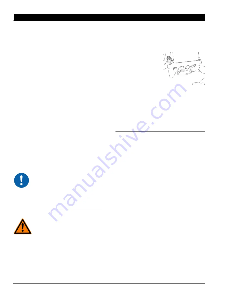
When first pressurizing the filter, it may be necessary to tighten
the lid/actuator rod seal. See
Figure 1. The viscosity of the
process fluid will determine
whether this is necessary. If
the seal begins to leak,
compress the seal by rotating
the packing wheel in one-sixth
of a turn increments. For
maximum seal life, do not use
excessive force to tighten the
packing wheel.
5.
Always pressurize the unit
slowly on start up and watch
for leakage.
6.
The unit is equipped with a plug in the lid for placement of
overpressure vent, for use as an air release and/or connection for
fluid filing of vessel.
7.
Monitoring of the differential pressure between the inlet and outlet
pressures should be used to determine stroking and purging
rates. Normal operation should exhibit low differential pressure
that is maintained throughout.
Operational Modes
Filtering
Dirty process fluid enters thru the inlet port, is pushed thru the filter
screen where contaminants are removed and clean process exits thru
the outlet port.
Cleaning
The cleaning process occurs periodically during the filtering process.
As the dirty process fluid passes thru the filter screen, contaminants are
collected on the inside of filter screen. The cleaning disc scrapes the
length of the filter screen and pushes the contaminants into the purge
chamber.
Purging
The purging process occurs to remove contaminants collected in the
purge chamber. Once the cleaning disc assembly reaches the bottom
of the housing, the purge valve is opened, forcing the concentrated
contaminants collected in the purge chamber out of the filter.
Reference Sequence Diagram and Control Philosophy for complete
details.
Figure 1


